How to Choose a Linear Stepper Motors?
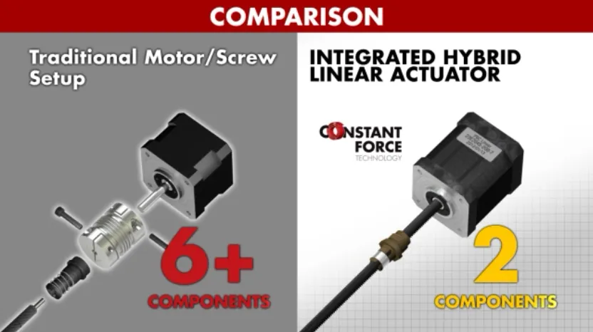
The linear stepping motor operates through the interaction between the magnetic rotor core and the pulsed electromagnetic field generated by the stator, resulting in the rotation of the motor. The conversion of this rotary motion into linear motion is achieved using the screw and nut technology employed within the motor. The inception of linear stepper motors can be traced back to the year 1968. Several typical examples of such motors are depicted in the figure below. 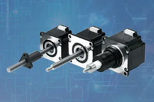 As a consequence of this development, the design undergoes significant streamlining, thereby facilitating the integration of straight-line stepper motors to attain high-precision linear motion without necessitating external mechanical linkages in numerous applications.
  In the context of developing linear motion-related products or solutions, we strongly suggest that engineers concentrate on the following aspects:
 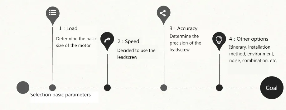 1. What is the load on the system? The load can be classified into two types: static load and dynamic load. The size of the load determines the motor's fundamental size. Static load refers to the maximum thrust that the screw can withstand when it is not in motion. Dynamic load refers to the maximum thrust that the screw can withstand when it is in motion. Hence, engineers must take into account both static and dynamic loads to determine the appropriate motor size for the system. 2. What is the linear running speed of the motor? The running speed of a linear motor is intricately linked to the lead of the screw. Specifically, the nut advances one lead when the screw rotates one complete turn. Engineers must carefully select the appropriate screw lead based on the desired speed of the system. In general, for lower speeds, screws with smaller leads are recommended. Conversely, for higher speeds, larger screws should be chosen to achieve optimal performance. 3. What is the accuracy requirement of the system? Screw precision: Linear precision, which refers to the discrepancy between the actual and theoretical stroke after the screw rotates the pitch circle, is the standard metric for assessing screw precision. Additionally, engineers should also consider repeated positioning accuracy, a crucial factor that determines the system's ability to reach the same position multiple times. Backlash: Backlash, the relative axial movement of the screw and nut when they are at rest, is a critical consideration in the development of linear motion systems. As the system operates over time, the backlash can increase due to wear. One way to compensate or correct for the increased backlash is to utilize a clearance nut. Engineers must pay particular attention to backlash when bidirectional positioning is required, as even minor discrepancies in position can result in significant errors. 4, other options Does the installation of linear stepper motors conform to the mechanical design? How will you connect moving objects to nuts? What is the effective stroke of the screw? What kind of driver is matched? Leveraging their extensive expertise and experience in the design, development, manufacturing, and marketing of hybrid stepper motors, as well as high-quality spindles and nuts, MOONS' has created the LE series of linear stepper motors. These motors are characterized by their external drive type, where the lead screw is integrated with the motor rotor as the motor output shaft. The nut, which is external to the motor, is coupled to the drive mechanism. As the motor rotates, the nut moves linearly along the screw. A standard or clearance nut can be used, depending on the application requirements. Additionally, the lead screw length can be customized to meet specific application needs. MOONS' LE series linear stepper motors offer a robust and versatile solution for a wide range of linear motion applications.
 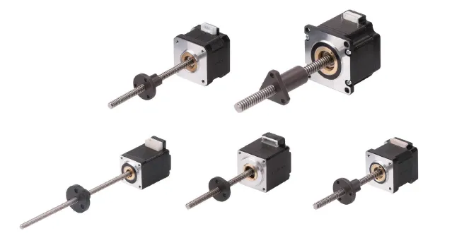 The external drive type linear stepper motor model is shown in the table below.
External nut linear stepper motors numbering system: 
MOONS' also introduced the LN series of through-axis and LC series push-rod linear stepper motors. 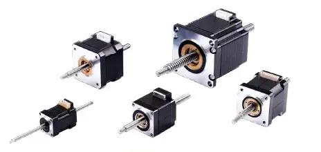 The lead-screw nut is an essential component of the motor rotor and is designed to enable linear motion along the lead screw. This type of motor is characterized by the integration of the nut and the lead screw, which passes through the center of the motor. As the motor rotates, it moves linearly along the lead screw. Furthermore, the lead screw can be completely detached from the motor and can be customized to any length required by the application. Engineers can choose to fix the motor in place so that the screw moves in and out of the motor, or the lead screw can be fixed so that the motor moves along the lead screw.
 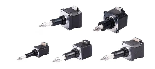 This motor design features an integrated lead-screw nut and a lead screw that drives an integral plunger in and out. The plunger is supported by a housing that is part of the motor, making it a complete assembly with a shaft that moves in and out. As a result, no separate supports are required for the screw or nut, simplifying installation and reducing system complexity. This design also offers greater design flexibility as it eliminates the need for additional components to support the lead screw or nut during the design process.
 As a consequence of this development, the design undergoes significant streamlining, thereby facilitating the integration of straight-line stepper motors to attain high-precision linear motion without necessitating external mechanical linkages in numerous applications.
  In the context of developing linear motion-related products or solutions, we strongly suggest that engineers concentrate on the following aspects:
  1. What is the load on the system? The load can be classified into two types: static load and dynamic load. The size of the load determines the motor's fundamental size. Static load refers to the maximum thrust that the screw can withstand when it is not in motion. Dynamic load refers to the maximum thrust that the screw can withstand when it is in motion. Hence, engineers must take into account both static and dynamic loads to determine the appropriate motor size for the system. 2. What is the linear running speed of the motor? The running speed of a linear motor is intricately linked to the lead of the screw. Specifically, the nut advances one lead when the screw rotates one complete turn. Engineers must carefully select the appropriate screw lead based on the desired speed of the system. In general, for lower speeds, screws with smaller leads are recommended. Conversely, for higher speeds, larger screws should be chosen to achieve optimal performance. 3. What is the accuracy requirement of the system? Screw precision: Linear precision, which refers to the discrepancy between the actual and theoretical stroke after the screw rotates the pitch circle, is the standard metric for assessing screw precision. Additionally, engineers should also consider repeated positioning accuracy, a crucial factor that determines the system's ability to reach the same position multiple times. Backlash: Backlash, the relative axial movement of the screw and nut when they are at rest, is a critical consideration in the development of linear motion systems. As the system operates over time, the backlash can increase due to wear. One way to compensate or correct for the increased backlash is to utilize a clearance nut. Engineers must pay particular attention to backlash when bidirectional positioning is required, as even minor discrepancies in position can result in significant errors. 4, other options Does the installation of linear stepper motors conform to the mechanical design? How will you connect moving objects to nuts? What is the effective stroke of the screw? What kind of driver is matched? Leveraging their extensive expertise and experience in the design, development, manufacturing, and marketing of hybrid stepper motors, as well as high-quality spindles and nuts, MOONS' has created the LE series of linear stepper motors. These motors are characterized by their external drive type, where the lead screw is integrated with the motor rotor as the motor output shaft. The nut, which is external to the motor, is coupled to the drive mechanism. As the motor rotates, the nut moves linearly along the screw. A standard or clearance nut can be used, depending on the application requirements. Additionally, the lead screw length can be customized to meet specific application needs. MOONS' LE series linear stepper motors offer a robust and versatile solution for a wide range of linear motion applications.
  The external drive type linear stepper motor model is shown in the table below.
 | Series | Frame size | Max Rated Thrust | Step size (μm) | Screw Length |
| LE08 | 20*20 | 13N | 3-12.7 | 30-150 |
| LE11 | 28*28 | 100N | 3.2-127 | 50-200 |
| LE14 | 35*35 | 125N | 3.9-127 | 50-200 |
| LE17 | 42*42 | 240N | 3.9-127 | 50-300 |
| LE23 | 57*57 | 444N | 5-127 | 100-400 |

| Series | E=External nut linear stepper motors |
| Motor Type | 17=42*42mm, Optional NEMA 8, 11, 14, 17, 23; 4S = body length code, please refer to the base size confirmation |
| Lead Screw Type | T0808=screw length 8mm, lead=8mm, Please refer to the catalog for specific parameters. |
| Screw Length | 100=100mm, Defined according to customer requirements, minimum 1mm increment |
| Nut Type | AR1=Round standard nut, apply for T0808; AR = Round standard nut, BR = Round anti-backlash nut, AT =Triangular standard nut, BT= Triangular anti-backlash nut, CN=Custom made nut. |
| Customized Code | S =Lead screw end machining; 0=No special custom, B=Brake, E=Encorder, C=Custom |
| Rated Current | XXX=X.XX(A) |
LN series Non-captive linear stepper motors
 The lead-screw nut is an essential component of the motor rotor and is designed to enable linear motion along the lead screw. This type of motor is characterized by the integration of the nut and the lead screw, which passes through the center of the motor. As the motor rotates, it moves linearly along the lead screw. Furthermore, the lead screw can be completely detached from the motor and can be customized to any length required by the application. Engineers can choose to fix the motor in place so that the screw moves in and out of the motor, or the lead screw can be fixed so that the motor moves along the lead screw.
 LC series Captive linear stepping motor
 This motor design features an integrated lead-screw nut and a lead screw that drives an integral plunger in and out. The plunger is supported by a housing that is part of the motor, making it a complete assembly with a shaft that moves in and out. As a result, no separate supports are required for the screw or nut, simplifying installation and reducing system complexity. This design also offers greater design flexibility as it eliminates the need for additional components to support the lead screw or nut during the design process.