* Free shipping to North America and most of Europe for orders of $100 or more


ID SSDC Series Step-Servo Drives
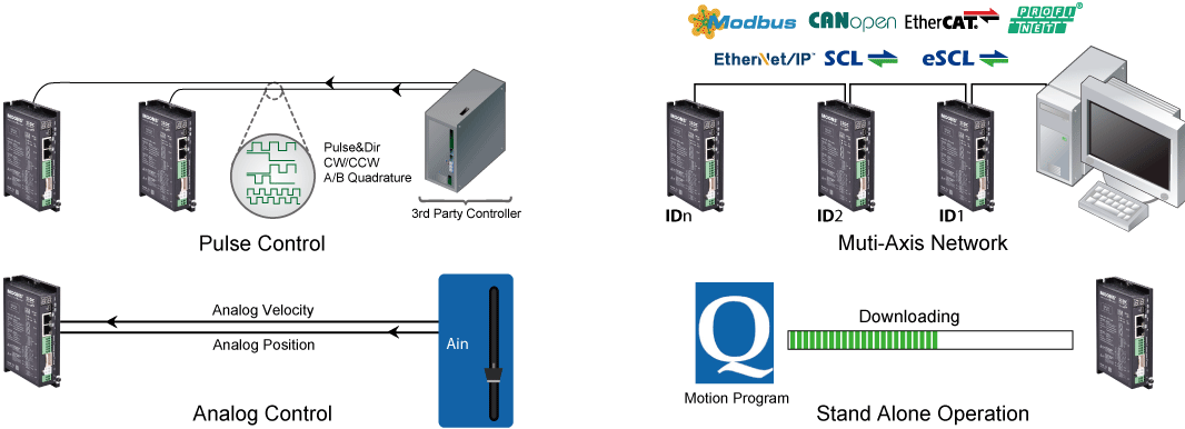
SSDC series is a high performance, intelligent Step-Servo system (Closed-Loop Stepper System) for multi-axes field bus control, Supporting pulse/direction control, analog control and multiple field bus controls such as Modbus, CANopen, SCL/eSCL commands, EtherNet/IP and EtherCAT protocol. And SSDC series also supports Stand-alone Programmable Function(Q programmer).
● Intelligent Built-in Stand-alone Programmable Controller
● Support Multi-axis Fieldbus Control
● Closed-loop Stepper System with Servo Technology
● Low Vibration, Low Noise, Low Heat
● Compact Size, High Torque, Long Working Life
● High Efficiency, High Precision, High Response
● Optimized interface orientation for easy wiring(SSDC06-EC-H)
● Support Multi-axis Fieldbus Control
● Closed-loop Stepper System with Servo Technology
● Low Vibration, Low Noise, Low Heat
● Compact Size, High Torque, Long Working Life
● High Efficiency, High Precision, High Response
● Optimized interface orientation for easy wiring(SSDC06-EC-H)


Brand Name: MOONS'
Price:
USD
221.0
-
358.0
EA
Payment Methods
 Buyer Protection:
 Free Exchange


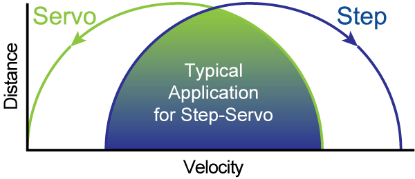
The SSDC series is a high performance, intelligent Step-Servo system with multi-axes field bus control.Enhancing a stepper motor with servo technology has created a product with exceptional features and broad capability. It supports pulse/direction control, analog control and multiple field bus controls such as Modbus, CANopen, SCL/eSCL commands, EtherNet/IP and EtherCAT protocol. And the SSDC series also supports the stand alone function(Q programmer) called by field bus control.
■ Multi-functional Capability
■ Closed-Loop Control
• Closed-loop Step-Servo mode
The step servo motor has a built-in high-resolution intelligent encoder. In addition to providing customers with accurate positioning, the drive can automatically identify the motor model and motor parameters after connecting the smart encoder motor, eliminating the need for motor configuration steps. At the same time, a drive can be compatible with a variety of intelligent encoder motors, and has two resolution encoders 20000 pulses/revolution and 4096 pulses/revolution to choose from, and it can also support multiple closed-loop control modes. Ordinary encoders only have A/B signals, and the initial alignment of the motor is achieved by energizing the motor windings and locking the shaft. If there is no friction load, the lock shaft alignment is more accurate. However, if there is a friction load (such as the application of a vertical axis), the initial alignment will produce an electrical angle error, which will cause a torque loss. The greater the friction load, the greater the torque loss. When the frictional load is large to a certain degree, it may cause the motor to fail to run or even speed up. In addition to the A/B signal, the intelligent encoder mounted on the MOONS' step servo motor also has an auxiliary positioning signal. The drive can know the exact position of the motor in real time. Even if there is a friction load, there will be no electrical angle error, and there will be no loss of torque.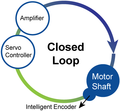
• Closed-loop Step-Servo mode
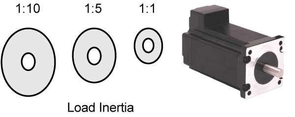
Position, velocity and current closed loop control. Precisely position and velocity control can match the harsh applications. Adjust the current in real time according to the actual load situation. Highly robust servo control accommodates a wide range of inertial loads and friction load changes.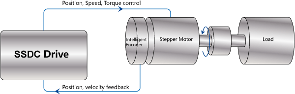
• Closed-loop Step mode
Position Closed-loop control. No tuning, no vibration,stall prevention. This mode is suitable for some special applications where the vibration is particularly demanding, such as vision systems, nano-technology, semiconductor manufacturing, ink jet printers, and so on. 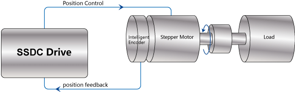
• Full Closed-loop mode - 2-way feedback
Support 2-way feedback, one way connect to the motor encoder position feedback, the other way connect to the load side position feedback, to avoid the position error caused by the mechanical error of the transmission mechanism, to achieve more precisely position control. Load side feedback support: single-ended or differential incremental encoder, scale.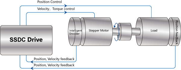
■ Safe & Convenient
• Support communication and motor power cables disconnection protection - Make equipments safer
• Support on-line configuration by fieldbus - Make operation more convenient
• Support on-line configuration by fieldbus - Make operation more convenient
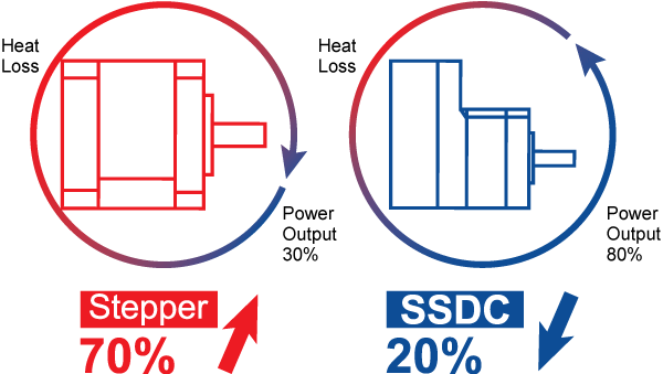
■ Low Heating / High Efficiency
• The SSDC uses only the current required by the application, generating minimum heat output.
• When the motor is not moving, the current can be nearly zero resulting in extremely low heat output.
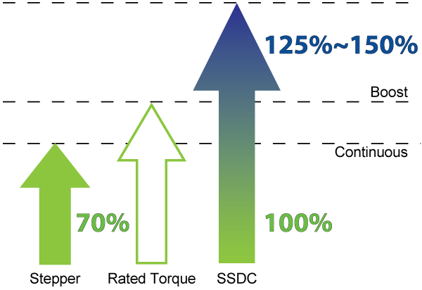
• Being able to use almost 100% of the available torque allows for more efficient operation and may allow a smaller motor size.
• When the motor is not moving, the current can be nearly zero resulting in extremely low heat output.
• Being able to use almost 100% of the available torque allows for more efficient operation and may allow a smaller motor size.
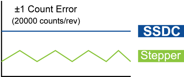
■ Smooth & Accurate
• Space vector current control with a high resolution encoder gives smooth and quiet operation, especially at low speeds - a feature not found with traditional stepper motors.
• High stiffness due to the nature of the stepper motor combined with the highly responsive servo control results in accurate position control both while running and when standing still.
• High stiffness due to the nature of the stepper motor combined with the highly responsive servo control results in accurate position control both while running and when standing still.
■ Fast Response
When performing fast point-to-point moves, the high torque output and advanced servo control provides a very responsive system far exceeding what can be done with a conventional stepper system.
■ High Torque
• Because the TSM operates in full servo mode, all the available torque of the motor can be used. The motor can provide as much as 50% more torque in many applications.
• High torque capability often eliminates the need for gear reduction.
• Boost torque capability can provide as much as 50% more torque for short, quick moves.
• High torque capability often eliminates the need for gear reduction.
• Boost torque capability can provide as much as 50% more torque for short, quick moves.
■ Motion Monitoring
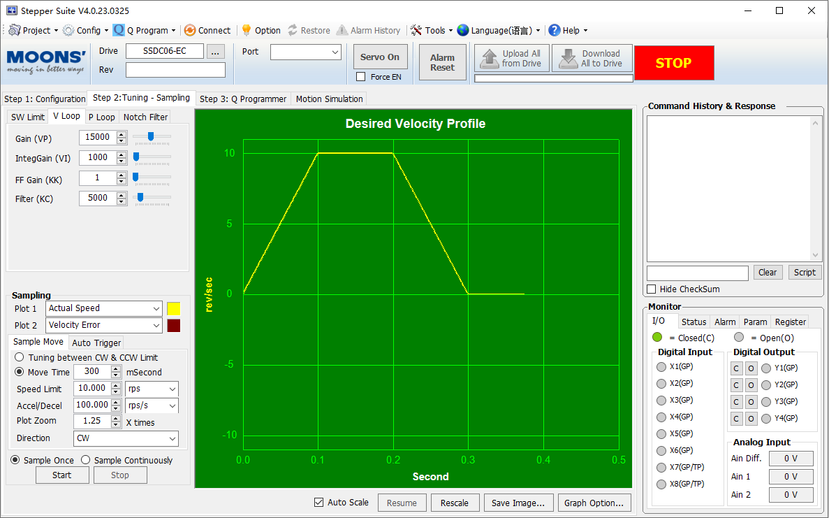
• For applications where extreme real-time motion is critical, the Step-Servo Quick Tuner provides a simple and practical tool for monitoring actual motion trajectories.
• It can be used to monitor common metrics such as actual velocity and position error to assess the current actual performance of the system.
• An interactive monitoring and tuning interface provides the fastest possible performance output.
• It can be used to monitor common metrics such as actual velocity and position error to assess the current actual performance of the system.
• An interactive monitoring and tuning interface provides the fastest possible performance output.
■ Easy Tuning
• Pre-defined tuning parameters quickly allow maximum control performance and stability.
• A selection list provides an easy method to achieve the desired level of control.
• In most cases NO extra manual tuning is required.
• There is no need to do tuning in closed- step mode.
• A selection list provides an easy method to achieve the desired level of control.
• In most cases NO extra manual tuning is required.
• There is no need to do tuning in closed- step mode.
■ Software
Stepper Suite• Friendly interface
• Easy setup in just three steps
• Servo parameter tuning and sampling
• Integrated Q programming interface
• Motion Simulation and monitoring
• Write and save SCL command scripts
• Integrated online help
• Support stepper and stepper servo series products
• Easy setup in just three steps
• Servo parameter tuning and sampling
• Integrated Q programming interface
• Motion Simulation and monitoring
• Write and save SCL command scripts
• Integrated online help
• Support stepper and stepper servo series products

RS485 Bus Utility• Stream SCL commands from the command line
• Simple interface with powerful capability
• Easy setup with RS-485 for 32 axis network motion control
• Monitoring Status of I/O, drive, alarm and the other nine most
• Useful motion parameters
• Write and save SCL command scripts
• Online help integrated
• Supports all RS-485 drives
• Simple interface with powerful capability
• Easy setup with RS-485 for 32 axis network motion control
• Monitoring Status of I/O, drive, alarm and the other nine most
• Useful motion parameters
• Write and save SCL command scripts
• Online help integrated
• Supports all RS-485 drives

CANopen Test Tool• Friendly User Interface
• Multiple operation Mode Support
• Multi-Thread, High Performance
• CAN bus monitor and log function
• Kvaser/PEAK adapter support
• Multiple operation Mode Support
• Multi-Thread, High Performance
• CAN bus monitor and log function
• Kvaser/PEAK adapter support
• All software applications run on Microsoft Windows 7, Windows 8, Windows 10, Windows XP(Service Pack 3) 32-bit or 64-bit systems
■ Software
□ Standard Series
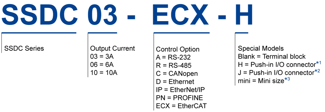
*1 :SSDC06/10-ECX-H, SSDC06-A-H Only
*2 :SSDC06/10-ECX-J Only
*3 :SSDC03-R-mini, SSDC06-ECX-mini Only
*2 :SSDC06/10-ECX-J Only
*3 :SSDC03-R-mini, SSDC06-ECX-mini Only
□ Multi-Axis Series

■ Ordering Information
| UL | Model | Current | Voltage※ | Multi-functional Capability | ||||||||
|---|---|---|---|---|---|---|---|---|---|---|---|---|
| Pulse | Analog | Modbus/RTU | CANopen | Modbus/TCP | EtherNet/IP | EtherCAT | Profinet | Q Program | ||||
| SSDC06-4X-ECX | 0.1-6.0A | 24-70VDC | √ | |||||||||
| SSDC10-4X-ECX | 0.1-10.0A | 24-70VDC | √ | |||||||||
| SSDC06-4X-ECX-S | 0.1-6.0A | 24-70VDC | √ | |||||||||
| SSDC10-4X-ECX-S | 0.1-10.0A | 24-70VDC | √ | |||||||||
| SSDC06-2XU-ECX | 0.1-6.0A | 24-70VDC | √ | |||||||||
| SSDC10-2XU-ECX | 0.1-10.0A | 24-70VDC | √ | |||||||||
| SSDC06-2XU-ECX-S | 0.1-6.0A | 24-70VDC | √ | |||||||||
| SSDC10-2XU-ECX-S | 0.1-10.0A | 24-70VDC | √ | |||||||||
| SSDC06-4XU-ECX | 0.1-6.0A | 24-70VDC | √ | |||||||||
| SSDC10-4XU-ECX | 0.1-10.0A | 24-70VDC | √ | |||||||||
| SSDC06-4XU-ECX-S | 0.1-6.0A | 24-70VDC | √ | |||||||||
| SSDC10-4XU-ECX-S | 0.1-10.0A | 24-70VDC | √ | |||||||||
| ★ | SSDC06-ECX-H | 0.1-6.0A | 24-70VDC | √ | √ | |||||||
| ★ | SSDC10-ECX-H | 0.1-10.0A | 24-70VDC | √ | √ | |||||||
| ★ | SSDC06-ECX-J | 0.1-6.0A | 24-70VDC | √ | √ | √ | ||||||
| ★ | SSDC10-ECX-J | 0.1-10.0A | 24-70VDC | √ | √ | √ | ||||||
| ★ | SSDC06-A-H | 0.1-6.0A | 24-70VDC | √ | √ | √ | ||||||
| ★ | SSDC10-A-H | 0.1-10.0A | 24-70VDC | √ | √ | √ | ||||||
| ★ | SSDC06-PN-01 | 0.1-6.0A | 24-70VDC | √ | √ | √ | ||||||
| ★ | SSDC10-PN-01 | 0.1-10.0A | 24-70VDC | √ | √ | √ | ||||||
| SSDC03-R-mini | 0.1-3.0A | 12-48VDC | √ | √ | ||||||||
| SSDC06-ECX-mini | 0.1-6.0A | 24-48VDC | √ | √ | ||||||||
| ★ | SSDC03-A | 0.1-3.0A | 12-48VDC | √ | √ | √ | ||||||
| ★ | SSDC06-A | 0.1-6.0A | 24-70VDC | √ | √ | √ | ||||||
| ★ | SSDC10-A | 0.1-10.0A | 24-70VDC | √ | √ | √ | ||||||
| ★ | SSDC03-R | 0.1-3.0A | 12-48VDC | √ | √ | √ | √ | |||||
| ★ | SSDC06-R | 0.1-6.0A | 24-70VDC | √ | √ | √ | √ | |||||
| ★ | SSDC10-R | 0.1-10.0A | 24-70VDC | √ | √ | √ | √ | |||||
| ★ | SSDC03-C | 0.1-3.0A | 12-48VDC | √ | √ | |||||||
| ★ | SSDC06-C | 0.1-6.0A | 24-70VDC | √ | √ | |||||||
| ★ | SSDC10-C | 0.1-10.0A | 24-70VDC | √ | √ | |||||||
| ★ | SSDC03-D | 0.1-3.0A | 12-48VDC | √ | √ | √ | √ | |||||
| ★ | SSDC06-D | 0.1-6.0A | 24-70VDC | √ | √ | √ | √ | |||||
| ★ | SSDC10-D | 0.1-10.0A | 24-70VDC | √ | √ | √ | √ | |||||
| ★ | SSDC03-IP | 0.1-3.0A | 12-48VDC | √ | √ | √ | √ | √ | ||||
| ★ | SSDC06-IP | 0.1-6.0A | 24-70VDC | √ | √ | √ | √ | √ | ||||
| ★ | SSDC10-IP | 0.1-10.0A | 24-70VDC | √ | √ | √ | √ | √ | ||||
※:SSDC06-2X/2XU continuous 4*6A, boost 4*7.5A(1.5s);SSDC10-2X/2XU continuous 4*10A, boost 4*15A(1.5s).SSDC06-4X/4XU continuous 4*6A, boost 4*7.5A(1.5s);SSDC10-4X/4XU continuous 4*10A, boost 4*15A(1.5s)。
★:UL certified models.
★:UL certified models.
■ Driver Specifications
□ Specifications
| Driver | SSDC03 | SSDC06 | SSDC10 |
|---|---|---|---|
| Input Voltage | 12-48VDC | 24-70VDC | 24-70VDC |
| Output Current | continuous 3A, boost 4A(1.5s) | continuous 6A, boost 7.5A(1.5s) | continuous 10A, boost 15A(1.5s) |
| Protection | Over-voltage, under-voltage, over-temp, motor/winding shorts (phase-to-phase, phase-to-ground) | ||
| Speed Range | Up to 3000rpm | ||
| Filters | Digital input noise filter, Analog input noise filter, Smoothing filter, PID filter, Notch filter | ||
| Non-Volatile Storage | Configurations are saved in FLASH memory on-board the DSP | ||
| Ambient Temperature | 0 to 40°C (32 to 104°F) when mounted to a suitable heatsink | ||
| Ambient Humidity | 90% Max., non-condensing | ||
| Mass | 0.25kg | ||
| Encoder Resolution | 20000 counts/rev( for AM17/23/24/34SS-N motors) 4096 counts/rev( for AM08/11/17/23/24/34RS motors) | ||
□ Technical specifications
| Type | EtherCAT | ||||||
|---|---|---|---|---|---|---|---|
| Driver | SSDC-4X-ECX | SSDC-4X-ECX-S | SSDC-2XU-ECX | SSDC-4XU-ECX | SSDC-ECX-mini | SSDC-ECX-H | SSDC-ECX-J |
| Digital Inputs | 5DI*4 | 5DI*4 | 3DI*2 | 3DI*4 | 5DI | 3DI | 5DI |
| Digital Outputs | 3DO*4 | 3DO*4 | 2DO*2 | 2DO*4 | 2DO | 1DO | 2DO |
| Analog Inputs | NO | NO | NO | NO | NO | NO | 1 analog inputs |
| Encoder Outputs | NO | NO | NO | NO | NO | NO | NO |
| +5V Output | NO | NO | NO | NO | NO | NO | 5VDC,100mA |
| Bus Control | EtherCAT | EtherCAT | EtherCAT | EtherCAT | EtherCAT | EtherCAT | EtherCAT |
| Counts/IO | NO | NO | NO | NO | NO | NO | NO |
| PLC(Q programmer) | NO | NO | NO | NO | YES | YES | YES |
| Type | RS485 | RS232 | CANopen | Ethernet | ||||
|---|---|---|---|---|---|---|---|---|
| Driver | SSDC**-R-mini | SSDC**-R | SSDC**-A | SSDC**-A-H | SSDC**-C | SSDC**-D | SSDC**-IP | SSDC**-PN |
| Digital Inputs | 2DI | 8DI | 8DI | 4DI | 8DI | 8DI | 8DI | 8DI |
| Digital Outputs | 1DO | 4DO | 4DO | 3DO | 4DO | 4DO | 4DO | 4DO |
| Analog Inputs | NO | 2 analog inputs | 2 analog inputs | NO | 2 analog inputs | 2 analog inputs | 2 analog inputs | 2 analog inputs |
| Encoder Outputs | NO | ABZ differential | ABZ differential | NO | ABZ differential | ABZ differential | ABZ differential | ABZ differential |
| +5V Output | NO | 5VDC,100mA | 5VDC,100mA | NO | 5VDC,100mA | 5VDC,100mA | 5VDC,100mA | 5VDC,100mA |
| Bus Control | Modbus/RTU SCL | Modbus/RTU SCL | SCL | SCL | CANopen | Modbus/TCP eSCL | Profinet Modbus/TCP eSCL | Ethernet/IP Modbus/TCP eSCL |
| Counts/IO | NO | YES | YES | YES | YES | YES | YES | YES |
| PLC(Q programmer) | YES | YES | YES | YES | NO | YES | YES | YES |
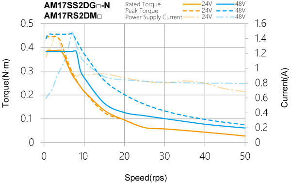
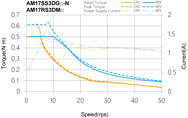
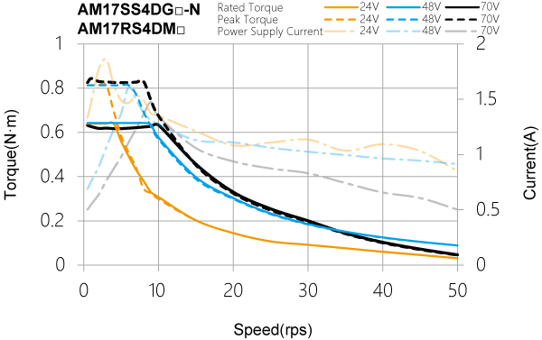
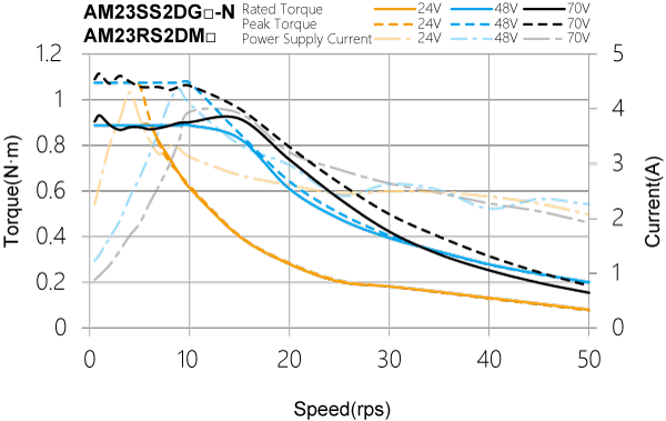
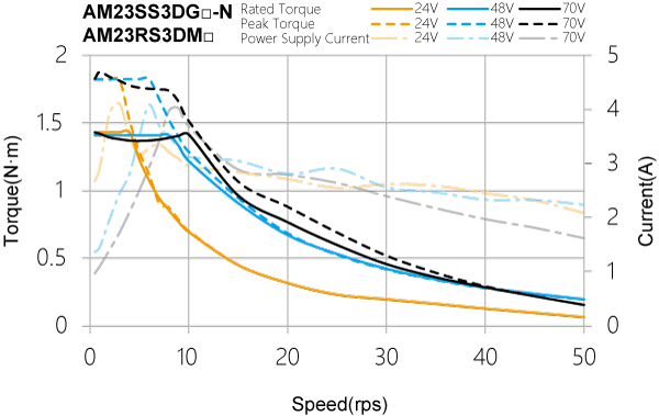
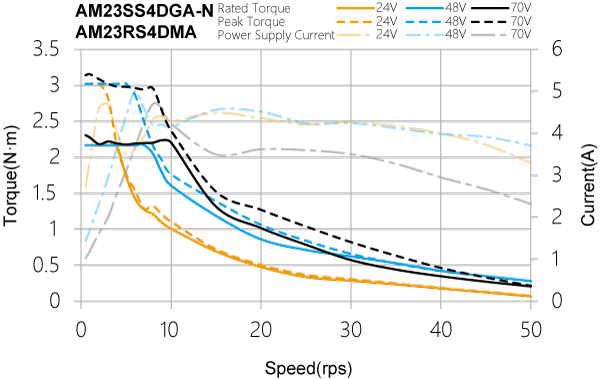
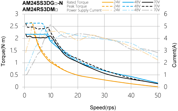
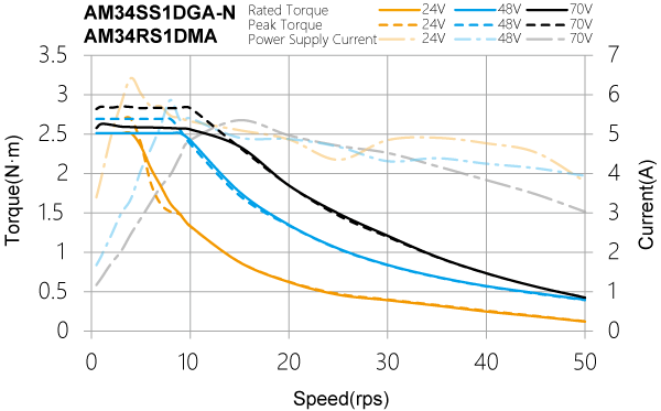
■ Recommended Motors
| Model | Drive P/N | Torque | Rotor Inertia | Encoder Resolution | Maximum Speed | Mass | Frame Size | Permissible Overhung Load(N) | Permissible Thrus Load | ||||
|---|---|---|---|---|---|---|---|---|---|---|---|---|---|
| Nm | gcm2 | counts/rev | RPM | g | mm | Distance(L) from Shaft End(mm) | |||||||
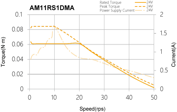
| AM11RS1DMA | SSDC03 | 0.065 | 9 | 4096 | 3600 | 118 | 28 | 20 | 25 | 34 | 52 | - | Less than the motor mass |
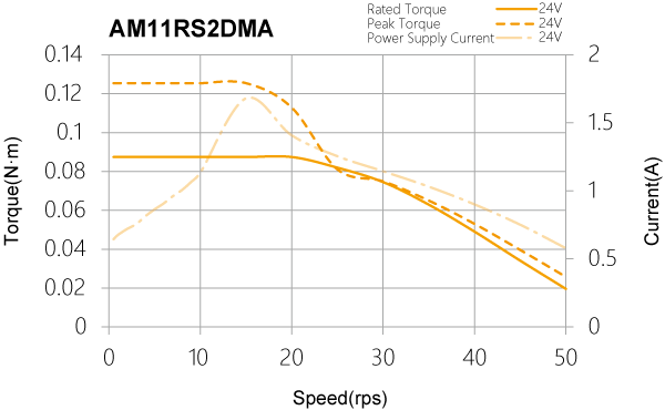
| AM11RS2DMA | 0.08 | 12 | 168 | ||||||||||
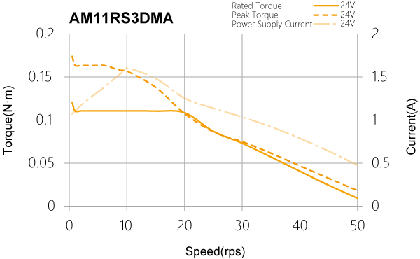
| AM11RS3DMA | 0.125 | 18 | 218 | ||||||||||
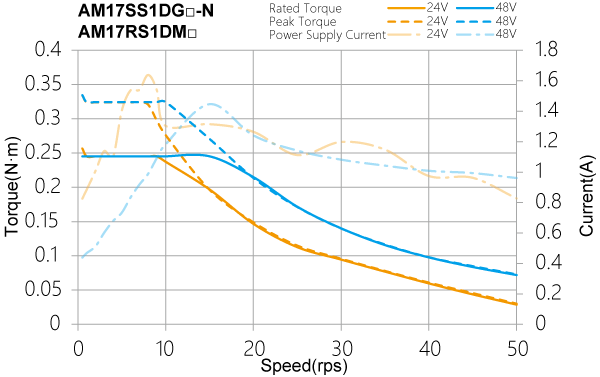
| AM17RS1DM □ | SSDC03 or SSDC06 | 0.26 | 38 | 4096 | 3600 | 390 | 42 | 35 | 44 | 58 | 85 | - | |
| AM17RS2DM □ | 0.42 | 57 | 440 | ||||||||||
| AM17RS3DM □ | 0.52 | 82 | 520 | ||||||||||
| AM17RS4DM □ | 0.7 | 123 | 760 | ||||||||||
| AM17SS1DG □ -N | 0.26 | 38 | 20000 | 3600 | 390 | ||||||||
| AM17SS2DG □ -N | 0.42 | 57 | 440 | ||||||||||
| AM17SS3DG □ -N | 0.52 | 82 | 520 | ||||||||||
| AM17SS4DG □ -N | 0.7 | 123 | 760 | ||||||||||
| AM23RS2DM □ | SSDC06 or SSDC10 | 0.95 | 260 | 4096 | 3600 | 850 | 56 | 63 | 75 | 95 | 130 | 190 | |
| AM23RS3DM □ | 1.5 | 460 | 1250 | ||||||||||
| AM23RS4DMA | 2.4 | 365 | 1090 | ||||||||||
| AM23SS2DG □ -N | 0.95 | 260 | 20000 | 3600 | 850 | ||||||||
| AM23SS3DG □ -N | 1.5 | 460 | 1250 | ||||||||||
| AM23SS4DGA-N | 2.4 | 365 | 1090 | ||||||||||
| AM24RS3DM □ | 2.5 | 900 | 4096 | 3600 | 1650 | 60 | 90 | 100 | 130 | 180 | 270 | ||
| AM24SS3DG □ -N | 2.5 | 900 | 20000 | 3600 | 1650 | ||||||||
| AM34RS1DMA | SSDC10 | 2.7 | 915 | 4096 | 3600 | 2000 | 86 | 260 | 290 | 340 | 390 | 480 | |
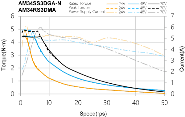
| AM34RS3DMA | 5.2 | 1480 | 3100 | ||||||||||
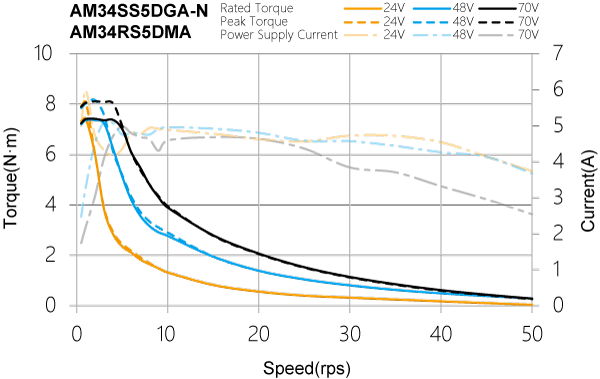
| AM34RS5DMA | 7.0 | 2200 | 4200 | ||||||||||
| AM34SS1DGA-N | 2.7 | 915 | 20000 | 3600 | 2000 | ||||||||
| AM34SS3DGA-N | 5.2 | 1480 | 3100 | ||||||||||
| AM34SS5DGA-N | 7.0 | 2200 | 4200 | ||||||||||
| 口:A 或B,详见电机命名规则 | |||||||||||||
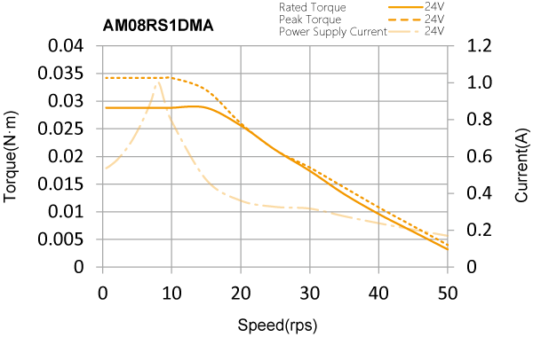
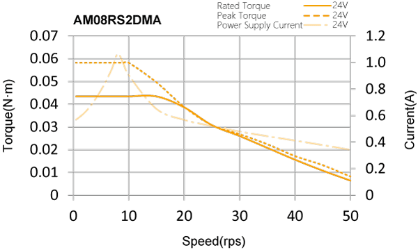
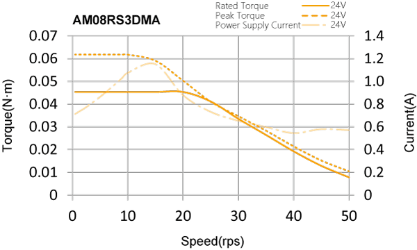
□ AM08RS Series
□ AM11RS Series
□ AM17SS/RS Series
□ AM23SS/RS Series
□ AM24SS/RS Series
□ AM34SS/RS Series
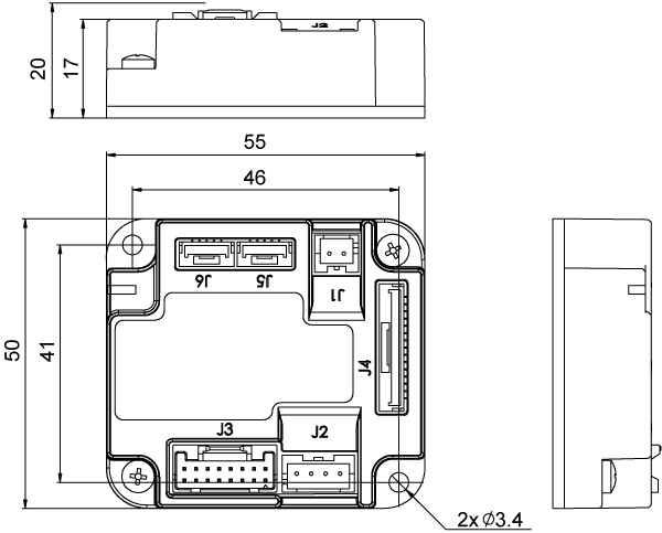
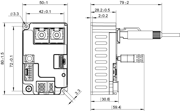
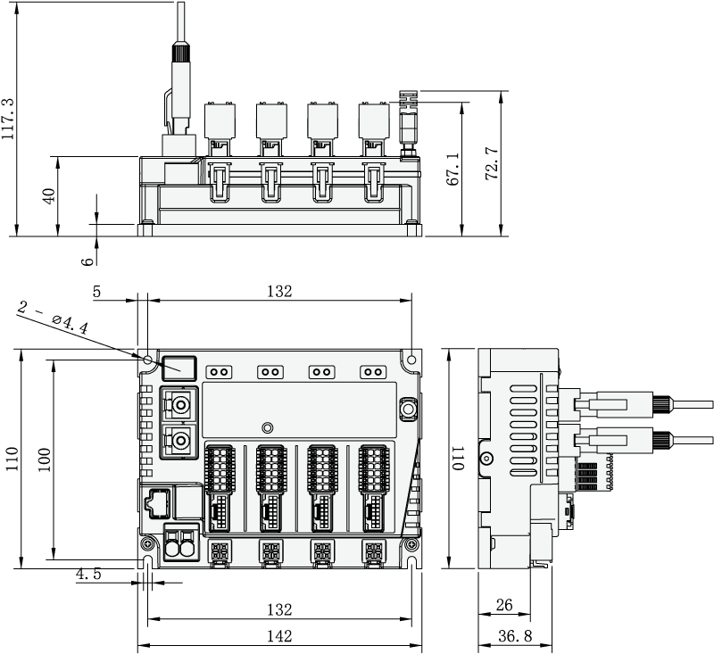
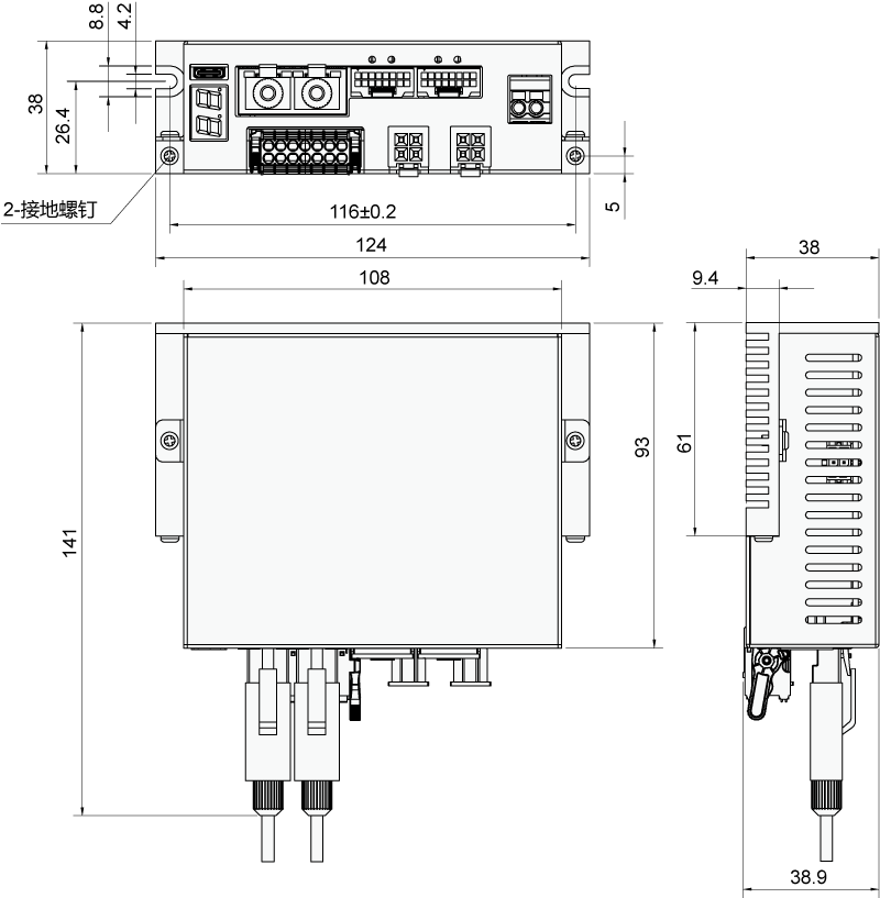
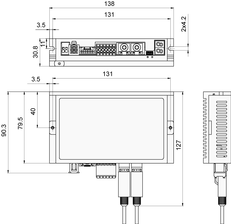
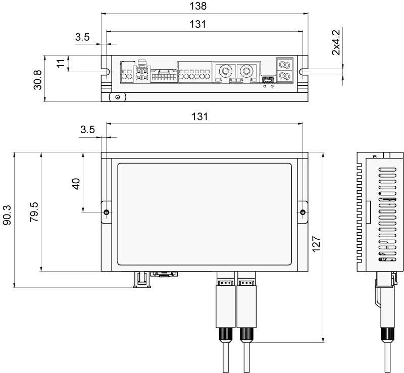
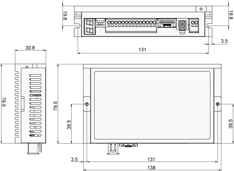
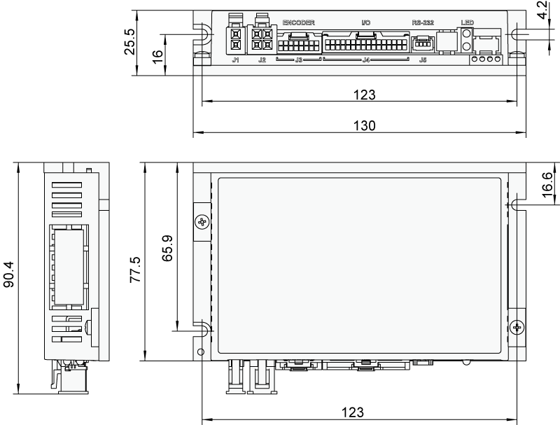
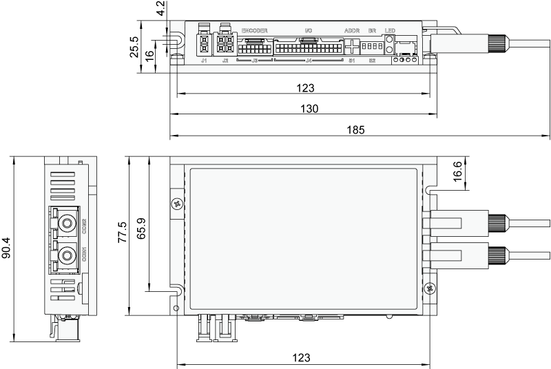
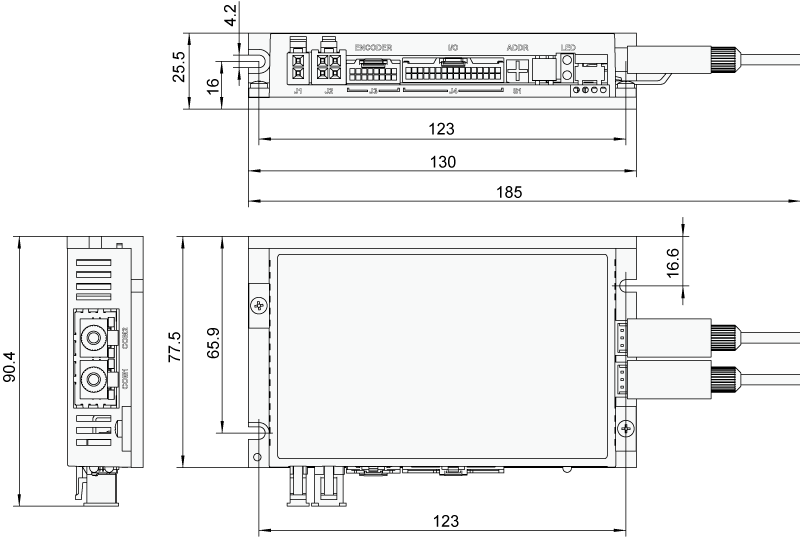
■ Driver Dimensions (Unit:mm)
□ SSDC03-R-mini
□ SSDC06-ECX_mini
□ SSDC06/10-4X-ECX, SSDC06/10-4X-ECX-S
□ SSDC06/10-2XU-ECX
□ SSDC06/10-4XU-ECX
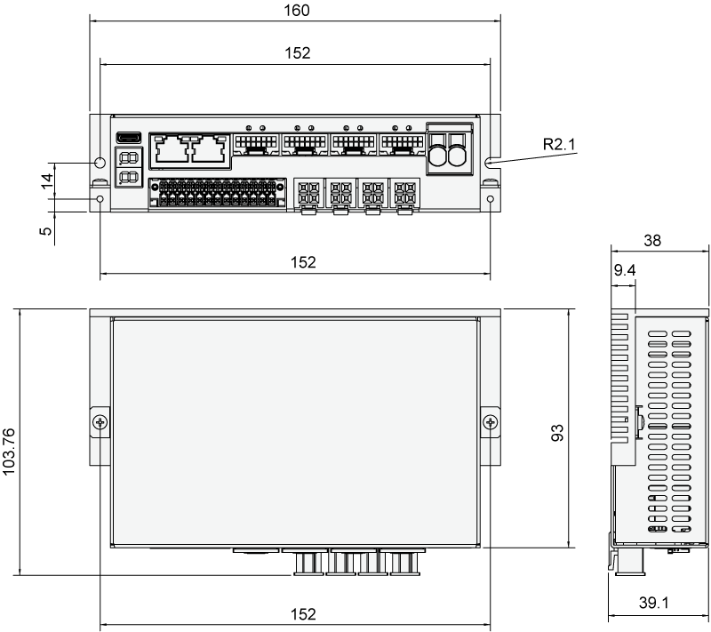
□ SSDC06/10-ECX-J
□ SSDC06/10-ECX-H
□ SSDC06/10-A-H
□ SSDC03/06/10-A
□ SSDC03/06/10-R,SSDC03/06/10-C
□ SSDC03/06/10-D/IP/PN
■ Motor Dimensions (Unit:mm)
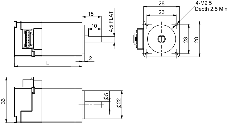
□ AM08 Series
| Model | L |
|---|---|
| AM08RS1DMA | 45.5 |
| AM08RS2DMA | 55.5 |
| AM08RS3DMA | 62.5 |
□ AM11 Series
| Model | L |
|---|---|
| AM11RS1DMA | 43.8 |
| AM11RS2DMA | 52.9 |
| AM11RS3DMA | 64.1 |

□ AM17 Series
| Model | A | A1 | B | B1 | L |
|---|---|---|---|---|---|
| AM17RS1DMA | φ6 | 5.5 | 20 | 15 | 59.5 |
| AM17RS1DMB | φ5 | 4.5 | 24 | 15 | 59.5 |
| AM17RS2DMA | φ6 | 5.5 | 20 | 15 | 65 |
| AM17RS2DMB | φ5 | 4.5 | 24 | 15 | 65 |
| AM17RS3DMA | φ6 | 5.5 | 20 | 15 | 73.5 |
| AM17RS3DMB | φ5 | 4.5 | 24 | 15 | 73.5 |
| AM17RS4DMA | φ6 | 5.5 | 20 | 15 | 89 |
| AM17RS4DMB | φ5 | 4.5 | 24 | 15 | 89 |
| AM17SS1DGA-N | φ6 | 5.5 | 20 | 15 | 59.5 |
| AM17SS1DGB-N | φ5 | 4.5 | 24 | 15 | 59.5 |
| AM17SS2DGA-N | φ6 | 5.5 | 20 | 15 | 65 |
| AM17SS2DGB-N | φ5 | 4.5 | 24 | 15 | 65 |
| AM17SS3DGA-N | φ6 | 5.5 | 20 | 15 | 73.5 |
| AM17SS3DGB-N | φ5 | 4.5 | 24 | 15 | 73.5 |
| AM17SS4DGA-N | φ6 | 5.5 | 20 | 15 | 89 |
| AM17SS4DGB-N | φ5 | 4.5 | 24 | 15 | 89 |
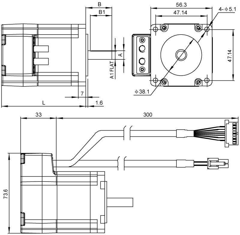
□ AM23 Series
| Model | A | A1 | B | B1 | L |
|---|---|---|---|---|---|
| AM23RS2DMA | φ8 | 7.5 | 24 | 20 | 77.5 |
| AM23RS2DMB | φ6.35 | 5.85 | 20 | 15 | 77.5 |
| AM23RS3DMA | φ8 | 7.5 | 24 | 20 | 99.5 |
| AM23RS3DMB | φ6.35 | 5.85 | 20 | 15 | 99.5 |
| AM23RS4DMA | φ8 | 7.5 | 24 | 20 | 102.5 |
| AM23SS2DGA-N | φ8 | 7.5 | 24 | 20 | 77.5 |
| AM23SS2DGB-N | φ6.35 | 5.85 | 20 | 15 | 77.5 |
| AM23SS3DGA-N | φ8 | 7.5 | 24 | 20 | 99.5 |
| AM23SS3DGB-N | φ6.35 | 5.85 | 20 | 15 | 99.5 |
| AM23SS4DGA-N | φ8 | 7.5 | 24 | 20 | 102.5 |
□ AM24 Series
| Model | A | A1 | B | B1 |
|---|---|---|---|---|
| AM24RS3DMA | φ10 | 9.5 | 24 | 20 |
| AM24RS3DMB | φ8 | 7.5 | 20.6 | 15 |
| AM24SS3DGA-N | φ10 | 9.5 | 24 | 20 |
| AM24SS3DGB-N | φ8 | 7.5 | 20.6 | 15 |

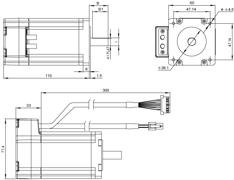
□ AM34 Series
| Model | L |
|---|---|
| AM34RS1DMA | 88 |
| AM34RS3DMA | 117.5 |
| AM34RS5DMA | 147 |
| AM34SS1DGA-N | 88 |
| AM34SS3DGA-N | 117.5 |
| AM34SS5DGA-N | 147 |
■ With Brake Motor Dimensions (Unit:mm)

□ AM17SS-N Series
| Model | A | A1 | B | L |
|---|---|---|---|---|
| AM17SS1DGA-N-BR01 | φ6 | 5.5 | 20 | 59.5 |
| AM17SS1DGB-N-BR01 | φ5 | 4.5 | 24 | 59.5 |
| AM17SS2DGA-N-BR01 | φ6 | 5.5 | 20 | 65 |
| AM17SS2DGB-N-BR01 | φ5 | 4.5 | 24 | 65 |
| AM17SS3DGA-N-BR01 | φ6 | 5.5 | 20 | 73.5 |
| AM17SS3DGB-N-BR01 | φ5 | 4.5 | 24 | 73.5 |
| AM17SS4DGA-N-BR01 | φ6 | 5.5 | 20 | 89 |
| AM17SS4DGB-N-BR01 | φ5 | 4.5 | 24 | 89 |
□ Specification of brake for NEMA17 motor
| Model | Voltage (VDC) | Torque (N.m) | Power (W) | Reactive time (ms) | Life (times) | Maximum speed (rpm) | Insulation class |
|---|---|---|---|---|---|---|---|
| NEMA17 Brake | 24 | 0.6 | 5 | 50 | 10000 | 5000 | Class B |

□ AM23SS-N Series
| Model | A | A1 | B | B1 | L |
|---|---|---|---|---|---|
| AM23SS2DGA-N-BR01 | φ8 | 7.5 | 24 | 20 | 77.5 |
| AM23SS2DGB-N-BR01 | φ6.35 | 5.85 | 20 | 15 | 77.5 |
| AM23SS3DGA-N-BR01 | φ8 | 7.5 | 24 | 20 | 99.5 |
| AM23SS3DGB-N-BR01 | φ6.35 | 5.85 | 20 | 15 | 99.5 |
| AM23SS4DGA-N-BR01 | φ8 | 7.5 | 24 | 20 | 102.5 |
□ Specification of brake for NEMA23 motor
| Model | Voltage (VDC) | Torque (N.m) | Power (W) | Reactive time (ms) | Life (times) | Maximum speed (rpm) | Insulation class |
|---|---|---|---|---|---|---|---|
| NEMA23 Brake | 24 | 1.2 | 4.5 | 50 | 10000 | 5000 | Class B |

□ AM24SS-N Series
| Model | A | A1 | B | B1 |
|---|---|---|---|---|
| AM24SS3DGA-N-BR01 | φ10 | 9.5 | 24 | 20 |
| AM24SS3DGB-N-BR01 | φ8 | 7.5 | 20.6 | 15 |
□ Specification of brake for NEMA24 motor
| Model | Voltage (VDC) | Torque (N.m) | Power (W) | Reactive time (ms) | Life (times) | Maximum speed (rpm) | Insulation class |
|---|---|---|---|---|---|---|---|
| NEMA24 Brake | 24 | 1.2 | 4.5 | 50 | 10000 | 5000 | Class B |

□ AM34SS-N Series
| Model | L |
|---|---|
| AM34SS1DGA-N-BR01 | 88 |
| AM34SS3DGA-N-BR01 | 117.5 |
| AM34SS5DGA-N-BR01 | 147 |
□ Specification of brake for NEMA34 motor
| Model | Voltage (VDC) | Torque (N.m) | Power (W) | Reactive time (ms) | Life (times) | Maximum speed (rpm) | Insulation class |
|---|---|---|---|---|---|---|---|
| NEMA34 Brake | 24 | 6.0 | 8.0 | 50 | 10000 | 5000 | Class B |
2D Drawings
3D Model
Quick Set-up Guide
| Title | Type | Size(KB) | Download |
|---|---|---|---|
| SSDC03-R-mini Quick Setup Guide_EN20240325.pdf | 514 |
Brochure
| Title | Type | Size(KB) | Download |
|---|---|---|---|
| SSDC Family Brochure_EN20251010 A13.pdf | 7498 |
User Manual
| Title | Type | Size(KB) | Download |
|---|---|---|---|
| Modbus RTU Manual_EN20171018.pdf | 1470 | ||
| HOST COMMAND reference uesr manual.pdf | 6963 | ||
| SSDC-D_IP Hardware Manual_EN20250819.pdf | 4118 | ||
| SSDC-R&C Hardware Manual_EN20250820.pdf | 4427 | ||
| EtherCAT UserManual EN20210427.pdf | 2260 | ||
| EtherCAT Multi Axis UserManual EN20260203.pdf | 2574 | ||
| SSDC-EC Hardware Manual_EN20210528.pdf | 6613 | ||
| SSDC-A Hardware Manual_EN20260128.pdf | 3395 | ||
| CANopen UserManual_EN20210816.pdf | 1238 | ||
| SSDC-ECX-H&J Hardware Manual_EN20250819.pdf | 4530 | ||
| SSDC-Multi Axis Hardware Manual_EN20260203.pdf | 2734 | ||
| SSDC06-ECX-mini Hardware Manual_EN20250820.pdf | 2787 |
Certification
| Title | Type | Size(KB) | Download |
|---|---|---|---|
| ROHS declaration-2026-A0.pdf | 178 | ||
| UL Certification for SSDC&STF Series Stepper Drives (STO).pdf | 261 | ||
| CE Certification for SSDC&STF Multi-Axis Series .pdf | 1662 | ||
| UKCA Certification for SSDC.pdf | 1613 | ||
| UL Certification for SSDC&STF Series Stepper Drives.pdf | 301 |
Software
| Title | Type | Size(KB) | Download |
|---|---|---|---|
| Stepper Suite Setup 4.0.25.1015.zip | ZIP | 24089 | |
| Step-Servo Quick Tuner Setup 3.0.19.0109.zip | ZIP | 37231 | |
| RS485 Bus Utility Setup 1.0.18.0510.rar | RAR | 1898 | |
| CANopen Test Tool Setup 1.0.23.0506.zip | ZIP | 10024 | |
| AMA Step-Servo EtherCAT v3.2.18.zip | XML | 190 | |
| SSDC-IP EDS.rar | RAR | 30 | |
| AMA MultiAxes StepServo EtherCAT v1.1.16.zip | XML | 100 | |
| CAN_EDS V310B_SSDC.eds | EDS | 45 | |
| GSDML-V2.33-AMP-port-multi-20201007.rar | XML | 2 |
EPLAN
Filter By Product Type
All ProductsExtended Encoder Cables
Extended I/O Cables
Extended Motor Cables
USB Configuration Cable
Communiaction Cable
Motor Types
Regen Clamp
RS485 Adapter


Delivery & Packaging
Ensure your ordered products are always safely packaged from easy click to fast delivery to your handsProfessional Product Label
Considering all possible harsh application environments, MOONS' specially designed labels for each product, which pass water-resistance test, durability rub test, high temperature resistance and corrosion resistance tests.Besides, our product labels are attached with QR code linking to product details, which is convenient for clients to view the detail product page with their mobile phones.
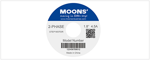
Note: This label design is suitable for products of stepper motor.
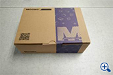
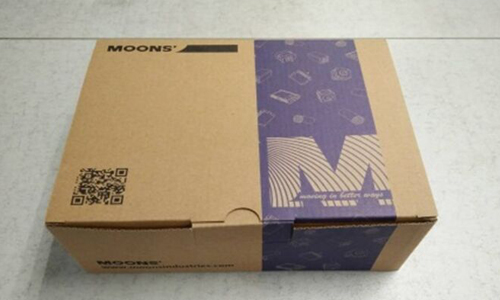
(Professional packing box and unique appearance design)
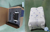
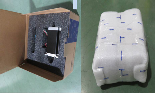
(Single item packed with EPE)
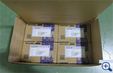
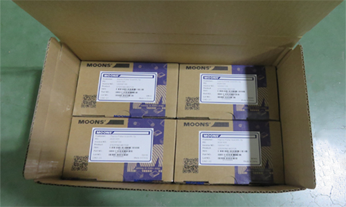
(Multi-products packed with another box)
Safely Packaging
In order to ensure your shipments withstand the long trip and arrive safely and intact, MOONS' specially designed Individual package to pass the drop test with its stable structure.Besides,the package is made from recyclable materials, providing you with professional safety delivery.
Whether just single item or multi-products the clients buy, all products are packed twice to avoid the damage further.
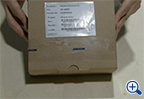
Shipping Visualization
For each case, products are carefully packed by experienced warehouse staff and the key processes are recorded by photos, which are then posted on our website, so that clients could clearly know the packing process and logistics status after placing order.
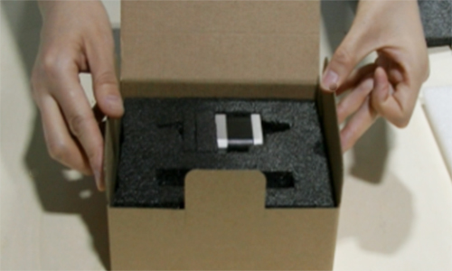
(Product in the box)


(Add the invoice)
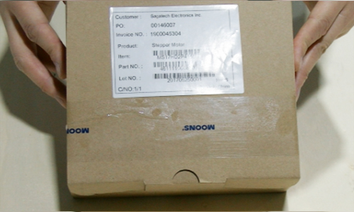
(Label the commodity)

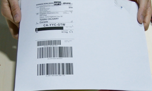
(The logistics waybill attached)

Fast Delivery
Fast Cross-Border DeliveryMOONS' chooses DHL as our main international express shipping partner. As the world's leading logistics specialist, DHL provides our customers with fast and professional inter- national door-to-door delivery service.
Estimated Delivery Time: e.g. China-USA major cities 3 business days.
Professional
Warehouse Management