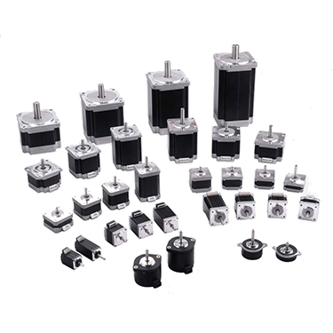
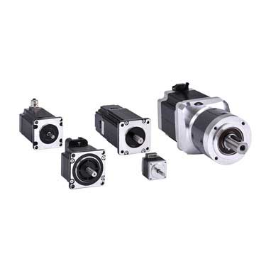
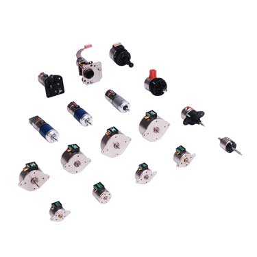
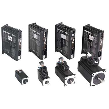
■ Stepper Motor Production Line
Hybrid Stepper Motors
Hybrid stepper motors provide excellent performance in areas of torque, speed, and step resolution. Typically, step angles for a hybrid stepper motor range from 200 to 400 steps per revolution. MOONS' stepper motors include standard hybrid stepper motors, PowerPlus hybrid stepper motors and high precision hybrid stepper motors and smooth hybrid stepper motors.
AM Series Stepper Motors
AM series hybrid stepping motors are mainly used in the industrial automation industry. They match the performance of MOONS' stepper drivers and they are the recommended stepper motor type for MOONS' stepper drivers.
AW Series Stepper Motors (IP65 Protection Type)
MOONS' has newly launched the AW Series industrial protective stepper motors to meet the demands of increasingly complex and harsh environment applications. The AW Series motor features a spray-coated housing that provides excellent waterproof performance and a sturdy, wear-resistant structure. The motor is designed with a compact structure and uses standard aviation connectors for more reliable connections.
5-Phase Hybrid Stepper Motors
This series of products is mainly based on five-phase motor, Step angle: 0.72°, High-precision design, Can achieve fast response
Permanent Magnet Stepper Motors
Compared to hybrid stepper motors, can stack stepper motors have a simpler design. The step angle is larger resulting in a cost effective motor with reduced physical dimensions.
Step-Servo Motors
Step-Servo motors are specifically designed to be paired with Step-Servo drives to create motor and drive combinations that outperform traditional step motor systems.
What is a stepper motor?
Stepper motor or step motor or stepping motor provide precise position and speed control, without the need for feedback devices to sense position. The operation of step motors is controlled through electrical pulses that the drive converts to current flowing through the windings of the motor. As the current is switched the motor rotates in precise steps of a fixed angle. The motor and drive constitutes a low cost control system that is precise and simple to construct.A stepper motor is a brushless DC electric motor that divides a full rotation into a number of equal steps. The motor's position can then be commanded to move and hold at one of these steps without any position sensor for feedback (an open-loop controller), as long as the motor is carefully sized to the application in respect to torque and speed.
Stepper motors, with their ability to produce high torque at a low speed while minimizing vibration, are ideal for applications requiring quick positioning over a short distance. Stepping technology allows for the use of an open-loop controller – simplifying machine design and lowering total cost compared to a servo motor system.
What are the types of stepper motors?
There are three main types of stepper motors: 1. Permanent magnet stepper motors, 2. Variable reluctance stepper motors, 3. Hybrid stepper motors.1. Permanent magnet stepper motors
Permanent magnet motors use a permanent magnet (PM) in the rotor and operate on the attraction or repulsion between the rotor magnet and the stator electromagnets.Pulses move the rotor clockwise or anticlockwise in discrete steps. If left powered at a final step, a strong detent remains at that shaft location. This detent has a predictable spring rate and specified torque limit; slippage occurs if the limit is exceeded. If the current is removed, a lesser detent still remains, holding the shaft position against spring or other torque influences. Stepping can then be resumed while reliably being synchronized with control electronics.
2. Variable reluctance stepper motors
Variable reluctance (VR) stepper motors have a plain iron rotor and operate based on the principle that minimum reluctance occurs with minimum gap, hence the rotor points are attracted toward the stator magnet poles.3. Hybrid stepper motors
Whereas hybrid stepper motors are a combination of the permanent magnet and variable reluctance types, to maximize power in a small size. Variable reluctance motors have detents when powered on, but not when powered off.Basic structure of stepper motor
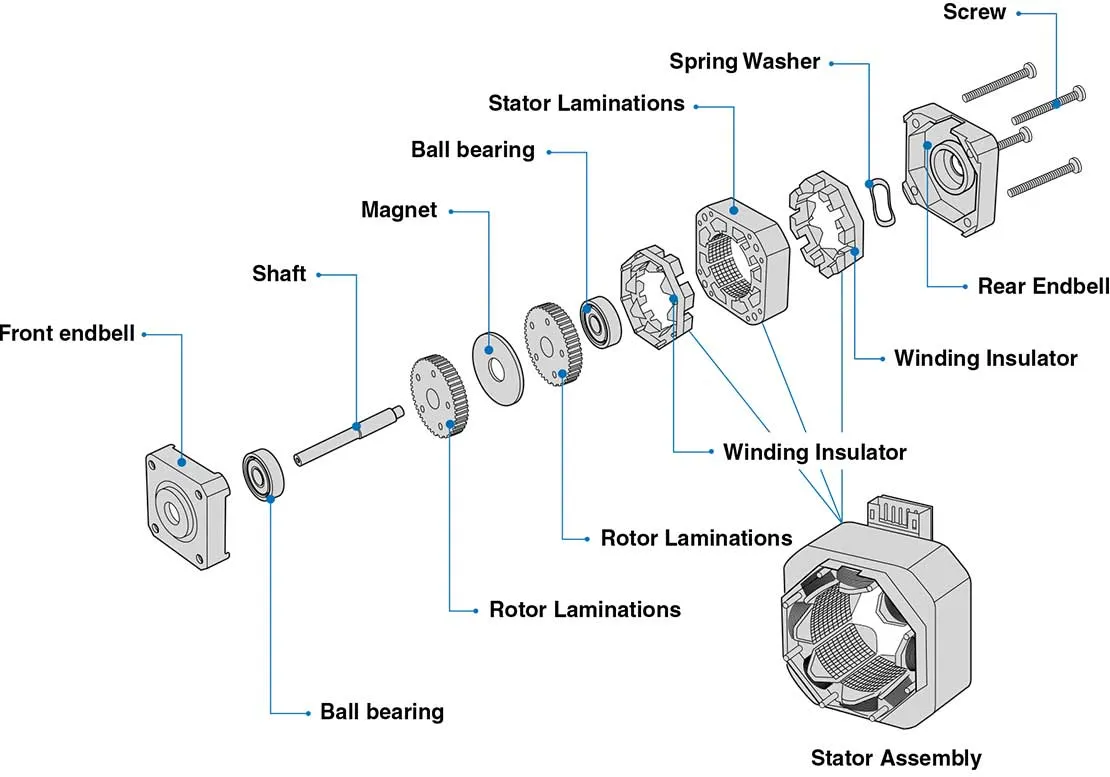
NEMA stepper motors
The US National Electrical Manufacturers Association (NEMA) standardizes various dimensions, marking, and other aspects of stepper motors, in NEMA standard (NEMA ICS 16-2001). NEMA stepper motors are labeled by faceplate size, NEMA 17 being a stepper motor with a 1.7 by 1.7 inches (43 mm × 43 mm) faceplate and dimensions given in inches. The standard also lists motors with faceplate dimensions given in metric units. These motors are typically referred to with NEMA DD, where DD is the diameter of the faceplate in inches multiplied by 10 (e.g., NEMA 17 has a diameter of 1.7 inches). There are further specifiers to describe stepper motors, and such details may be found in the ICS 16-2001 standard.Ringing and resonance of stepper motors
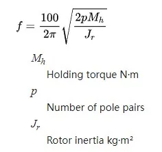
When the motor moves a single step it overshoots the final resting point and oscillates around this point as it comes to rest. This undesirable ringing is experienced as motor rotor vibration and is more pronounced in unloaded motors. An unloaded or under loaded motor may, and often will, stall if the vibration experienced is enough to cause a loss of synchronization.Stepper motors have a natural frequency of operation. When the excitation frequency matches this resonance the ringing is more pronounced, steps may be missed, and stalling is more likely. The motor resonance frequency can be calculated from the formula:
What is a chopper drive for a stepper motor?
A chopper drive addresses the problem of obtaining high torque at high speed from a stepper motor by turning the output voltage to the motor on and off rapidly (aka “chopping”) to control the motor current. At each step of the motor, a very high voltage is applied to the motor windings. This causes the current to rise rapidly, according to the relationship between current rise and inductance. It also allows higher current to be produced, according to Ohm's law.Current in a chopper drive is regulated by a current-sensing resistor placed in series with each winding. As current increases, a voltage develops across the resistor, and a comparator monitors this voltage level. At a predetermined reference voltage, the output voltage is turned off (chopped) until the next pulse takes place. In this way, current builds and declines as the voltage switches off and on, resulting in the proper average current per step cycle. This enables precise control of torque, regardless of variations in the power supply voltage. It also gives the shortest possible time for current build-up and decline.
Although a chopper drive requires additional electronics to monitor current in the windings and to control voltage switching, it allows a stepper motor to produce higher torque at higher speeds than a traditional L/R drive.
What is the operating principle of a stepper motor?
In response to each individual control pulse and direction signal,the drive applies power to the motor windings to cause the rotor to take a step forward, a step in reverse, or hold in position. Forexample, in a 1.8 degree two phase step motor: When both phases are energized with DC current, the motor will stop rotating and hold in position. The maximum torque the motor can hold in place with rated DC current, is the rated holding torque. If the current in one phase is reversed, the motor will move 1 step (1.8 degrees) in a known direction.If the current in the other phase had been reversed, the motor would move 1 step (1.8 degrees) in the other direction. As current is reversed in each phase in sequence, the motor continues to step in the desired direction. These steps are very accurate. For a 1.8 degree step motor, there are exactly 200 steps in one revolution.
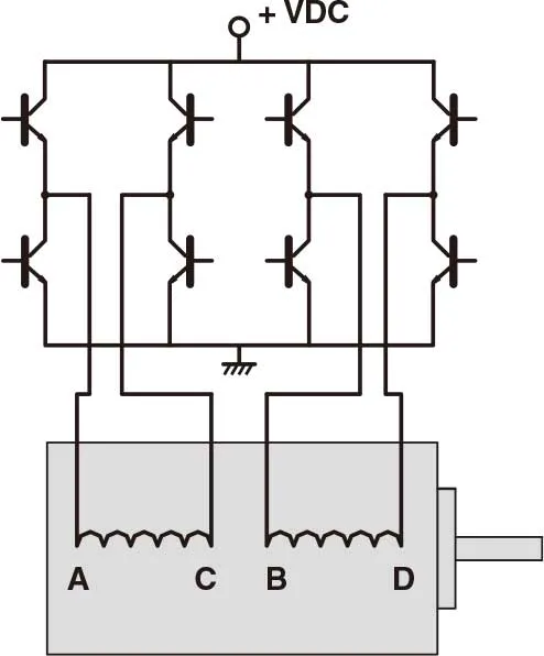
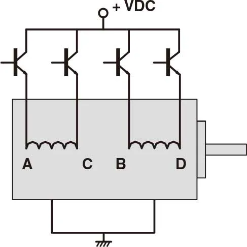
Two phase stepping motors are furnished with two types of windings: bipolar or unipolar. In a bipolar motor there is one winding on each phase. The motor moves in steps as the current in each winding is reversed. This requires a drive with eight electronic switches. In a unipolar motor there are two windings on each phase. The two windings on each phase are connected in opposite directions. Phase current is reversed by turning on alternate windings on the same phase. This requires a drive with only four electronic switches. Bipolar operation typically provides 40% more holding torque than unipolar, because 100% of the winding is energized in the bipolar arrangement.
- 2 phase step motor with bipolar driver
- 2 phase step motor with unipolar driver
What are the features of a stepper motor?
Precise Positioning Control
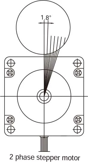
A stepper motor rotates with a fixed step angle, just like the second hand of a clock. This angle is called "basic step angle." MOONS' offers several types of "basic step angle" as standard motors: 2-phase stepping motors with a basic step angle of 0.9° and 1.8° and 3-phase stepping motors with a basic step angle of 1.2°.Besides the standard motor, MOONS' also has stepper motors avalible with other "basic step angle." They are 0.72°, 1.5°, 3.6° and 3.75°, these motors are not listed in this catalogue, please contact MOONS' for details.
Easy Control with Pulse Signals
A system configuration for high accuracy positioning is shown below. The rotation angle and speed of the stepping motor can be controlled accurately using pulse signals from the controller.
What is a Pulse Signal?
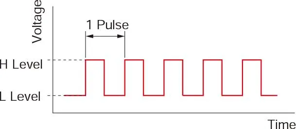
A pulse signal is an electrical signal whose voltage level changes repeatedly between ON and OFF.Each ON/OFF cycle is counted as one pulse. A command with one pulse causes the motor output shaft to turn by one step.
The signal levels corresponding to voltage ON and OFF conditions are referred to as "H" and "L," respectively.
The length of Rotation is Proportional to the Number of Pulses
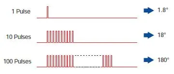
The length of rotation of the stepping motor is proportional to the number of pulse signal (pulse number) given to the driver.The relationship of the stepper motor's rotation (rotation angle of the motor output shaft) and pulse number is expressed as follows:

The Speed is Proportional to the Pulse Frequency
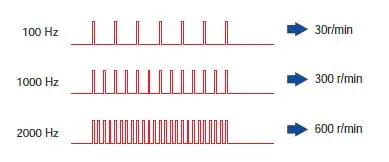
The speed of the stepper motor is proportional to the frequency of pulse signals given to the driver.The relationship of the pulse frequency [Hz] and motor speed [r/min] is expressed as follows:

Generating High Torque with a Compact Size
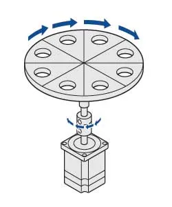
Stepper motors generate high torque with a compact size.These features give them excellent acceleration and response, which in turn makes these motors well-suited for torque-demanding applications where the motor must be started and stopped frequently.
To meet the need for greater torque at low speed, MOONS' also has geared motors option.
Frequent Starting/Stopping is Possible
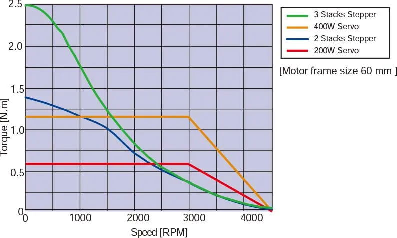
Speed VS Torque Characteristics comparetion between servo and stepper with same motor size.
The Motor Holds Itself at a Stopped Position
Stepper motor has full torque at stand-still as long as the windings are energized. This means that the motor can be held at a stopped position without using a mechanical brake.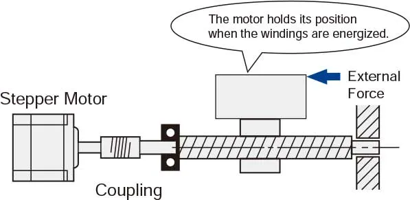
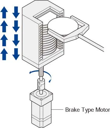
Motor with Electromagnetic Brake
Once the power is cut off, the self-holding torque of the motor is lost and the motor can no longer be held at the stopped position in vertical operations or when an external force is applied. In lift and similar applications, an electromagnetic brake type motor is required.Closed Loop Servo Control Stepper Motors
The Step-Servo is an innovative revolution for the world of stepping motor, it enhances the stepping motor with servo technology to create a product with exceptional feature and broad capability.The Step-Servo greatly improves the performance to be much more Intelligent, Efficient, Compact, Accurate, Fast and Smooth.

The applications of stepper motors
ApplicationsMOONS' stepping motors are widely used to create the motion needed in many types of equipment.
Examples include:

Why choose MOONS' stepper motors?
These step motors from MOONS' include a number of improvements for even greater performance and value: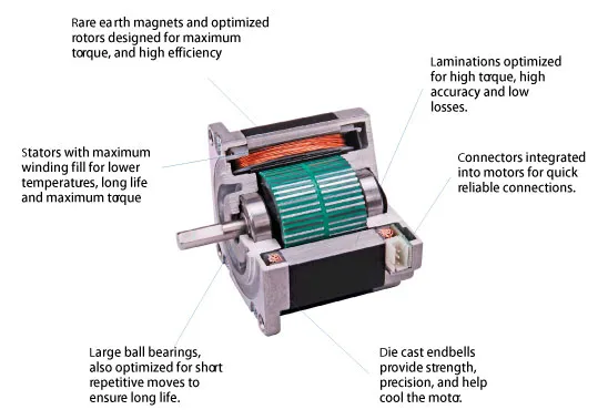
Custom motors
MOONS' provides motors to meet the needs of many applications.Common modifications include:
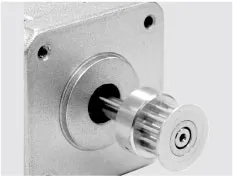
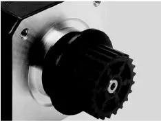
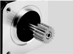
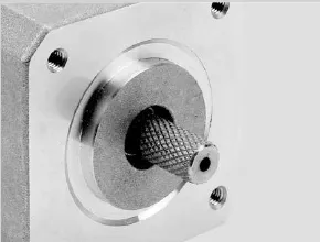
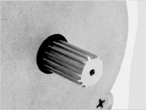
Press Fit Pulley & Gear
- Metal Pulley
- Plastic Pulley
- Gear
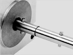
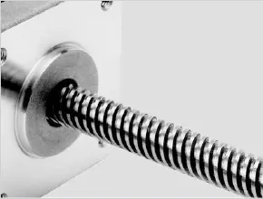
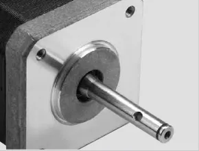
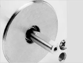
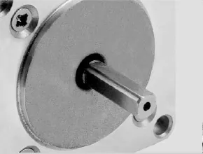
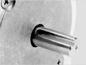
Shaft Options
- Dowel
- Worm Shaft
- Cross Drilled Shaft
- Single Flat
- Double Flat
- Key Way
- Knurl
- Hobbed Gear
- Helical Cut

