Introduction to MOONS' DALI LED Driver
DALI Dimming Curve
As per the DALI protocol, the dimming curve can be categorized into two distinct types: the logarithmic dimming curve and the linear dimming curve. Both dimming curves are comprised of 255 levels ranging from 0% to 100%, with the levels ranging from level 0 to level 254.
However, different from linear dimming curves, the logarithmic dimming curve focuses on subdividing low-end output (output below 20%); to be specific, current under the circumstance that the output between 20% and 100% only takes 59 dimming levels.
The standard logarithmic dimming curve defined by the DALI protocol is shown below.
1. Logarithmic Curve Logarithmic CurvePlease refers to the above figure. In the case that the light is not dimed to off, the percent taken by the minimum output current can be 0.1%. 2. Linear Curve Linear Curve the range from 0% to 100% is divided into 255 levels. In the case that the light is not dimed to off, the percent taken by the minimum output current can be 0.4% and the difference between every two levels is 0.039%.
Introduction to S Series LED Driver
Amplitude dimming is available for currents above 200mA, while it is PWM dimming for 0~200mA. The corresponding frequency is 3.6 kHz.

Programming Methods
As for MOONS' intelligent driver, two programming methods have been proposed successively. It includes cable programming as well as NFC (Near Field Communication) programming. Parameters of the LED driver can be modified, such as output current, minimum dimming level, color temperature range, etc.1. Cable Programming
It is not necessary to electrify the driver when programming the driver through MCS ports.The driver should be electrified when it is programmed through DALI ports.
For more information about cable programming please click here.

2. NFC Programming
For NFC programming, there is no need to electrify the driver.For further information about NFC programming please click here.

Firmware Upgrade
1. 64pcs S series DALI driver can be updated simultaneously through Smartkey and DALI power supply.
During the updating process, all drivers should be electrified.Unicast and broadcast upgrades take 2 and 4 minutes respectively.
2. 30pcs S series DALI driver can be updated simultaneously through Smartkey.
During the updating process, all drivers should be electrified.Unicast and broadcast upgrades take 2 and 4 minutes respectively.


Wiring Connection of Signal Line
Besides the ordinary wiring method (bus), MOONS' DALI driver also supports daisy chain wiring.1. Ordinary Wiring Method
All signal lines of the power supply should be connected to the bus, which makes it inconvenient for implementation.2. Daisy Chain Wiring Method
Compared with LED driver in the market, MOONS' DALI LED driver owns 2 group DALI signal ports, which supports Daisy Chain connection. Daisy chain connection implements to be easy and convenient.


Auxiliary Output Function
The LED driver is equipped with 12V/150mA auxiliary output to supply power for some DC input devices. In this way, one adapter can be spared. Note, the DC device in the figure is a MOONS' two channels 0-10V WIFI module.

DALI Bus Power Supply Function
Several models of the S series power supply are equipped with a DALI bus power supply that operates at 15V-100mA.The DALI sensor generally works with the DALI Master and is powered by the DALI auxiliary power supply. However, the DALI power supply is unnecessary for some applications like a closed-loop control system, one DALI bus power supply can be spared.
 DALI±ports of the DALI driver can provide power (15V,100mA) to the DALI sensor and dimmer. However, this kind of DALI driver cannot work with DALI Master. Because the additional capacity on the DALI bus will lead signal to be disturbed and DALI Master being broken.
Over Temperature Protection (NTC)
Considering that the heat dissipation effects of some lamps are poor, which is more likely to result in overheating of the LED chip to further damage it, the LED driver is equipped with an MCS± port exclusively used to externally connect an NTC thermistor.When the temperature of the lamp panel goes beyond the limited temperature value you set, the LED driver will decrease the current to 50%. When the risk (over-temperature) is removed, the driver will recover the output.


DALI DT8 Tunable White
According to DALI 209 protocol, using 1 DALI address to control lamp's color temperature and intensity.1. Parameters Settings

(1) Set driver's output current value.
The program of the driver is based on Power (channel 1)÷Power(channel 2)=1, So please make sure power of the warm LEDs and cold LEDs are same. If the Vf of warm LEDs and cold LEDs are different, you can input different current value.
Ch1±connects to cold LEDs. Ch2±connect to warm LEDs.
For example:
Ch1: the Vf of warm LEDs is 35.7V, you can set current to be 700mA, the power is 25W.
Ch2: the Vf of cold LEDs is 25.4V, you can set current to be 1000mA, the power is 25W.
(2) Select dimming strategy to be DT8 CCT Driver.
(3) Choose dimming curve to be linear or logarithmic.
(4) Set the minimum dimming level, the minimum value is 0.1%.
If you set the value to be 10%, the minimum intensity percentage equals 10%.
(5) AUX Enable: enable or disable driver's auxiliary output function.
If enable this function, the standby power dissipation>0.5W.
If disable this function, the standby power dissipation<0.5W.
(6) Physical CCT: input the value according to CCT lamp's parameters.
(7) Logical CCT: the actual CCT range can be achieved by driver and CCT lamp.
For example: The physical CCT of LED is 2700K and 6500K according to CCT lamp's parameters.
If you want the actual effect to be 3000~6000K, when driver works with CCT lamp, please set the logical CCT to be 3000K and 6000K.
2. Wiring Connection

(2) For this kind application, please ensure both DALI Master and control panel supports DALI DT8 function.
DALI DT6 Tunable White
One dual channel DALI driver owns 2 DALI addresses, one DALI address is responsible for controlling two channel's output to mix different color temperature. Another DALI address is responsible for total intensity controlling. 1. Parameters Settings

(1) Set driver's output current value.
The program of the driver is based on Power (channel 1)÷Power(channel 2)=1, So please make sure power of the warm LEDs and cold LEDs are same. If the Vf of warm LEDs and cold LEDs are different, you can input different current value.
Ch1±connects to cold LEDs. Ch2±connect to warm LEDs.
For example:
Ch1: the Vf of warm LEDs is 35.7V, you can set current to be 700mA, the power is 25W.
Ch2: the Vf of cold LEDs is 25.4V, you can set current to be 1000mA, the power is 25W.
(2) Select dimming strategy to be DT8 CCT Driver.
(3) Choose dimming curve to be linear or logarithmic.
(4) Set the minimum dimming level, the minimum value is 0.1%.
If you set the value to be 10%, the minimum intensity percentage equals 10%.
(5) AUX Enable: enable or disable driver's auxiliary output function.
If enable this function, the standby power dissipation>0.5W.
If disable this function, the standby power dissipation<0.5W.
(6) Physical CCT: input the value according to CCT lamp's parameters.
(7) Logical CCT: the actual CCT range can be achieved by driver and CCT lamp.
For example: The physical CCT of LED is 2700K and 6500K according to CCT lamp's parameters.
If you want the actual effect to be 3000~6000K, when driver works with CCT lamp, please set the logical CCT to be 3000K and 6000K.
2. Wiring Connection

(2) One driver owns 2 addresses. One address is responsible of controlling output of two channels to achieve color temperature. Another one address is responsible of controlling output of two channels to achieve intensity.
(3) When you connect drivers with the DALI Master. Each channel of the driver will be set an random address. Then DALI Master use binary search method to find the lowest random address X, once find it, and set X to be A0Y. And exclude it from the searching process. Then DALI Master to search address X+1, once find it, set X+1 to be A0Y+1.
(4) By implementing this internal algorithm together with the controller's binary search method, the address A0Y and A0Y+1 control one lamp's intensity and color temperature. If you want to change address number, make sure that new address B0Y and B0Y+1 keep consecutive. Like the general DALI DT6 driver, each address can store 16 scenes. Address A0Y control the scene of intensity, while address A0Y+1 controls the scene of color temperature.
(5) Only address A0Y can response to broadcast command. The address (A0+1) won't react broadcast command.
DALI DT6 Solo Dimming
One dual channel DALI driver owns 1 DALI address. This address controls both two channels. The current value of Ch1 and Ch2 can be set to be different. 1. Parameters Settings

Under the circumstance that no overpower situation exist, any current value can be set for channel1 and channel 2. 2. Wiring Connection

DALI DT6 Dual Dimming
One dual channel DALI driver owns 2 DALI addresses. These two addresses control two channels separately. The current value of Ch1 and Ch2 can be set to be different. 1. Parameters Settings

Under the circumstance that no overpower situation exist, any current value can be set for channel1 and channel 2. 2. Wiring Connection
Matching List of DALI Master
Although DALI is a standard interface protocol, tests have been conducted in detail targeted at the following DALI master to guarantee 100% matching without any error.
The Outline of LED Driver
To make it convenient for LED driver to be applicable to diverse installation environments, MOONS' LED driver has 6 types of shells, among which, 4 are built-in and 2 are independent.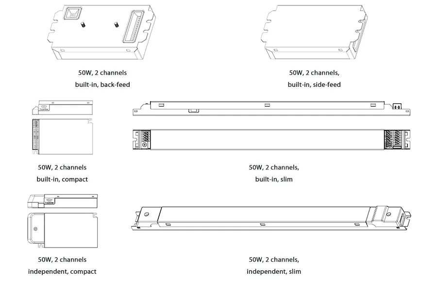
Related Products
MOONS' has been involved in the processes of designing, engineering and manufacturing LED light drivers for many years. As a global leading LED driver developer, MOONS' has made and continuous to investment in deep dimming high performance architectural products. We are pleased to introduce the latest designs innovative products. The DALI dual dimmer controlled intelligent, programmable LED drivers provide the smoothest flicker-free high-performance dimming to dark for every fixture. The new "S" series of LED drivers is available in multiform factors to provide a perfect match for your luminaire.

|
|
MU050S150BQI511 DALI dual dimming Flicker-Free dimming Dimming range: 0.1%~100% Compact |