Three-phase stepper motor principle
Before explaining the working principle of the three-phase stepping motor, it is necessary to understand the structure of the three-phase stepping motor. The following is an introduction to the structure of the three-phase stepping motor.
The stepper motor (VR type or reactive or variable reluctance type) whose rotor does not use permanent magnets has been used in three-phase stepper motors for a long time. In 1986, a stepping motor with permanent magnets on the rotor and teeth on the stator poles was developed. The combination of the tooth pitch of the stator and the rotor can obtain higher angular resolution and torque. The number of main poles of the stator coil of the three-phase stepping motor is a multiple of three, so the number of main poles of the stator of the three-phase stepping motor is 3, 6, 9, 12, etc.
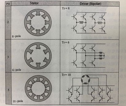
The figure below is a comparison of the typical stator structure and drive circuit of stepper motors with different numbers of phases, ignoring the rotor structure diagram. It is assumed that the rotors are all PM type or HB type, and the corresponding rotors are equipped for two-phase, three-phase and five-phase according to the stator. The stator adopts a structure with few main poles that does not generate unbalanced electromagnetic force, that is, when two phases have 4 main poles, three phases have 3 main poles, and five phases have 5 main poles, unbalanced electromagnetic force will be generated in the structure. The structure of the stator in the figure is a simple structure with 8 main poles for two phases, 6 main poles for three phases, and 10 main poles for five phases.

Three-phase stepper motor principle
On the other hand, the number of power tubes of the bipolar stepper motor drive circuit is 8 for the two-phase stepper motor driver, 10 for the five-phase stepper motor driver, and the three-phase motor is connected by Y or △ because the windings are connected. Therefore, considering the integration of the motor and the driver, the structure of the three-phase stepping motor is simple, and the manufacturing cost of both is very low.
Judging from the parity of the number of stator phases, the number of switching power tubes in the drive circuit in the odd-numbered case is less than that in the even-numbered case, for example, a three-phase stepping motor has fewer driving power tubes than a two-phase stepping motor. Compared with the two-phase stepping motor, the three-phase stepping motor has the advantages of 1.5 times higher resolution and lower vibration when the number of rotor teeth is the same, so the number of use will increase and the price will be reduced. There are dozens of MOONS' three-phase stepper motors to choose from: https://www.moonsindustries.com/c/stepper-motors-a02/filter/phase-3
Three-phase stepper motor principle
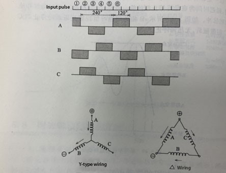
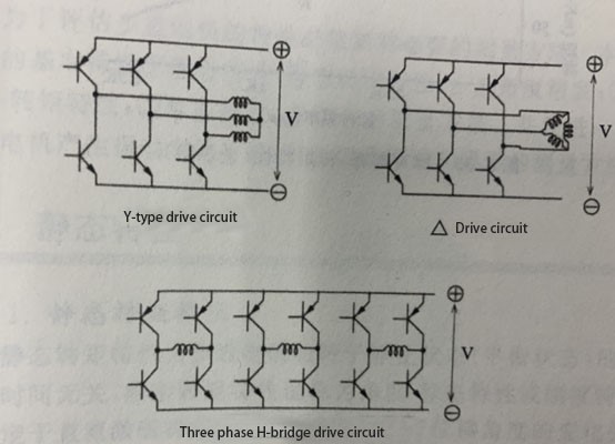
The phase windings of the three-phase stepping motor have Y connection and △ connection, and 6 power tubes are used to form the drive circuit. The excitation sequence of the drive circuit is driven, and the voltage waveform applied to each phase coil is shown in the figure below.

Excitation sequence and three-phase wiring
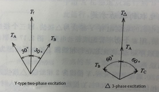
As shown in the figure above, the Y connection is 2-phase excitation, and the △connection is 3-phase excitation. When the number of turns of the 1-phase winding is N, Y is connected, and the torque TY when each phase current I flow in is the same as the torque T△ of the △ connection. From the vector diagram of the 2-phase excitation and the 3-phase excitation in the figure below, the following is deduced calculation formula. It must be noted that the total current of the△wiring is √3I.
TY=2NIcos30° = √3NI
T△=(2/3)N(√3I)+(2/3)N(√3I)cos60° = √3NI

Excitation method and synthesis torque
The excitation current of the △wiring is √3 times that of the Y wiring, and the speed is higher than that of the Y wiring method. The above figure shows the three-phase wiring method and its driving circuit. In addition to the Y wiring and the △ wiring, there is also a three-phase independent winding drive, also known as the H-bridge driving method. Now, these three circuits are driven by the same voltage, the Y connection is a two-phase winding in series relationship, the voltage is applied to the two-phase series winding, the inductance of the series winding increases, and its reactance wL increases together with the motor speed, resulting in a decrease in current, reduce torque.

Three-phase stepper motor principle
Voltage V is applied to each coil in the three-phase independent winding drive (also called H bridge), which is the driving method that can perform high-speed rotation among the three. But the number of power tubes is 2 times of Y or △, a total of 12.
Among these driving methods, Y and △ connections are very commonly used. Now we take a 42mm, 33mm long, and 3.75° step angle HB stepping motor as an example for comparison. For example, the current value of the △ connection method is √3 times, the two have the same torque at low speed, but the △ connection method is better at high speed.
