How to control Stepper motor speed?
With the advancement of electronic technology, microprocessors have become widely used in the control of stepper motors. Various microprocessors are currently employed for this purpose, such as the S51 series, MSP430 series, DSP series, and drive card series, etc. However, their control principle are fundamentally similar. The following analysis primarily focuses on the 89C51 microcontroller as an example to explore the stepper motor speed control.
Controlling the speed of a stepper motor involves regulating the duration of each power-on state. This can be achieved in two ways: one is the software delay method, and the other is the timer interrupt method.
How to control Stepper motor speed?
1. Software delay method
This method of controlling the stepper motor speed involves calling a delay subroutine after each power-on state transition. Once the delay ends, the phase-changing subroutine is executed again. Repeating this process allows the stepper motor to operate at a fixed speed. For example, executing the following program will cause the stepper motor to rotate continuously in the forward direction. To adjust the speed, simply modify the values of data1 and data2.
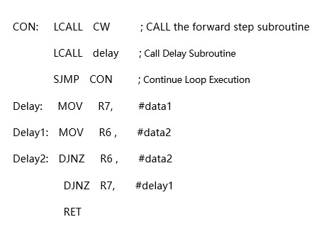
The delay time of the Delay program is: t=[1 +(1 + 2 x data2 + 2)x data1 ] + 2 x T
In this formula, T represents the machine cycle. When the 89C51 microcontroller uses a 6MHz crystal oscillator, T=2μs. If a 12MHz crystal oscillator is used, T=1μs.
The characteristics of the software delay method are as follows: by changing the value of data1 and data2 or calling different delay subroutines, different speed control can be achieved. It features simple programming and consumes fewer hardware resources. However, its drawback is that it uses too much CPU time, which is why it is typically employed only in simple control processes.
2. Timer interrupt method
Since the software delay method for controlling stepper motor speed consumes too much CPU time, the timer delay method is typically used in complex control systems. In this method, the timer is loaded with an appropriate initial value. After a certain period, the timer overflows, generating an interrupt signal that temporarily suspends the execution of the main program and triggers the execution of the timer interrupt service routine, creating a hardware delay. If the stepper motor commutation subroutine is placed within the timer interrupt service routine, the motor will commutate once each time the timer interrupts. The motor's speed can be controlled by adjusting the timer’s initial value. Since the commutation occurs within the interrupt service routine, it consumes less CPU time, allowing the CPU to perform other tasks.
The following section introduces the speed control subroutine using the T0 timer in 89C51 microcontroller as an example. Assume the timer operates in mode 1, and the motor's running speed is set to 1000 pulses per second, resulting in a commutation period of 1ms. With the 89C51 using a 12MHz crystal oscillator, the machine cycle is 1μs. Therefore, the T0 timer should be interrupted once every 1000 (03E8H) machine cycles. Since T0 is performing an addition count, after reaching 0FFFFH, adding one more will cause an overflow interrupt. Thus, the initial value loaded by T0 should be 10000H-03E8H, which is 0FC18H. With this initial value, executing the addition count 1000 times will cause an overflow. The interrupt service routine is as follows:
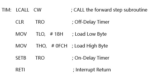
When debugging the above program, you may find that the motor speed is lower than the set value and lacks sufficient accuracy. To achieve precise timing, you should also account for the factors such as the loading time, start and stop timer, interrupt response time, and make necessary adjustment.
The following is the TIM1 subroutine that can accurately perform timing. To allow real-time changes to the load value, the load value is stored in the intermediate units R6 and R7. To account for the interrupt response time, the load value is added to the original count value, which continues to increment after the timer overflows. Additionally, the delay of 7 machine cycles T from the instruction cycle, which occurs between the CLR TR0 to SETB TFO instructions in the program. Therefore, when the commutation period is 1ms, the load value in R7 and R6 should be 0FC18H+07H, that is, 0FC1FH. The specific program is as follows:
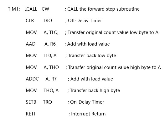
When this interrupt service routine is executed repeatedly, the stepper motor will run accurately at the specified frequency. By modifying the values in R6 and R7, the motor's speed can be adjusted
What is the general speed of the stepper motor?
The speed range of stepper motors is relatively wide, as follows:
Common speed range: The speed of typical stepper motors usually falls between tens and hundreds of revolutions per minute, making them suitable for many general industrial applications, such as automation equipment, printing machinery, textile machinery, etc.
High-speed application speed: In scenarios requiring high-speed operation, such as fast positioning or high-speed movement, high-speed stepper motors can achieve speeds of several thousand revolutions per minute or even higher.
No-load speed: For standard two-phrase stepper motors, the no-load speed can reach between 1000-2000 revolutions per minute.
Rated load speed: Under rated load conditions, the speed of stepper motors typically ranges from 0-1000 revolutions per minute.
Stepper motor speed calculation formula
The calculation of the stepper motor speed can be based on different known parameters, using various formulas for stepper motor speed calculation:
1. Calculations based on pulse frequency and step angle
The stepper motor is an open-loop device that converts electrical pulse signals into angular or linear displacement. With each pulse signal input, the motor rotates a fixed angle (step angle). The motor speed formula can be calculated using the pulse frequency and step angle:

The unit of speed "n" is r/min, the unit of pulse frequency "f" is Hz, and the unit of step angle "θ" is degree (°).
The derivation process of the stepper motor speed calculation formula:
A. Since f pulses are input per second, and each pulse causes the motor to rotate θ degrees, the motor's rotation angle per second is θf degrees;
B. Since there are 60 seconds in a minute and 1 revolution equals 360 degrees, the motor's revolutions per minute (r/min) of the motor is equal to (the angle of revolution per minute) ÷ (360 degrees), as shown in the formula above.
2. Situation based on segmentation drivers
The subdivision driver can further subdivide the step angle of the stepper motor. The subdivision factor allows for more accurately control the motor’s rotation. The subdivision multiple needs to be considered when calculating the speed. The formula is:
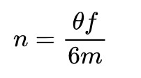
The unit of speed "n" is r/min, the unit of pulse frequency "f" is Hz, the unit of step angle "θ" is degree (°), and the number of subdivisions is m.
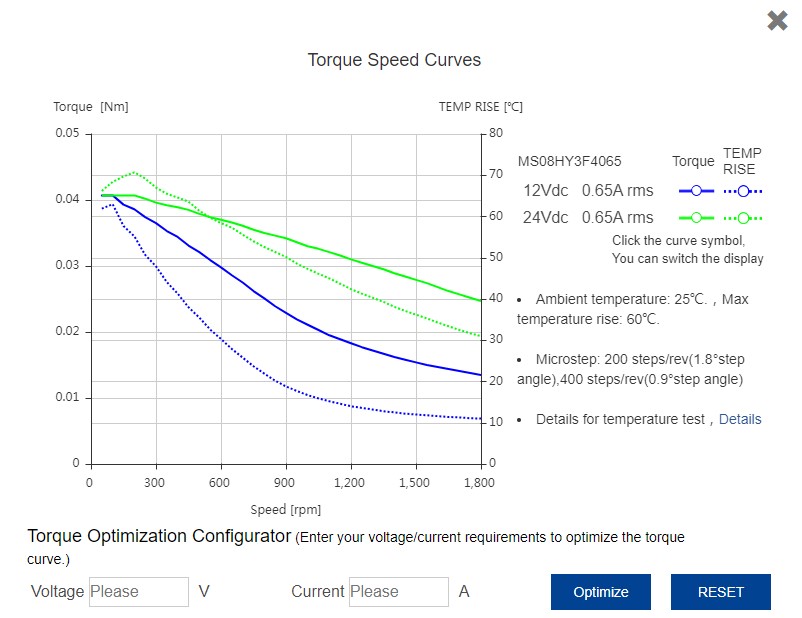
The above discusses the speed of stepper motors. The speed of MOONS' stepper motor products can be calculated using the hybrid stepper motor selection tool, and there is no need for manual calculation, as shown in the figure below. (Selection tool: https://www.moonsindustries.com/searchrobot)
