- Home
- Technical College
- SERVO MOTORS
- How to Reduce Electromagnetic Interference in Low-Voltage Servo Systems
How to Reduce Electromagnetic Interference in Low-Voltage Servo Systems
Servo driver uses high-speed switching elements inside, which will generate high frequency or low frequency during normal operation interference, and interfere with peripheral equipment through conduction or radiation. There is also a low-voltage unit inside the servo drive, which is likely to be disturbed by the noise of the peripheral equipment of the drive. A disturbed signal may cause the device to behave unexpectedly.
To prevent mutual electromagnetic interference between the servo drive and its peripheral devices, the following countermeasures can be taken.
• Make sure that the driver and motor are well grounded, and the grounding wire should. Preferably be a cable of AWG10 or above.
• Do not use the same sleeve for the main circuit cable and the input / output signal cable / encoder cable, and do not bundle them together. When wiring, the main circuit cable and the input / output signal cable / encoder cable should be separated by more than 30cm.
• For input/output signal cables and encoder cables, use twisted-pair wires or multi-core twisted pair shielded wires.
• The length of the input and output signal cables is less than 3m, and the encoder cable is less than 5m.
• Do not use the same power source as an electric welding machine, electric discharge machine, etc. Even if it is not the same power supply, when there is a high-frequency generator nearby, connect a noise filter to the input side of the main circuit power supply cable and the control power supply cable.
1. Ground
Good grounding treatment can give full play to the effect of EMI filter and greatly reduce interference.
• Must be grounded at a single point in parallel.
• Power extension cable between driver and motor, use cable with shielded mesh.
• The shielding net of the motor power line must be grounded and connected to the ground terminal of the drive.
2. Shielding of Motor Cables
The selection of motor cables with shielding nets and properly installed shielding nets can achieve better EMC effects and interference suppression effects. Please note the following:
• Use shielded cable (Better if there is a double-layer isolation layer)
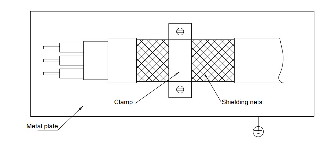
• The shielding nets at both ends of the motor cable must be grounded with the shortest distance and maximum contact area. Use clamps to fix the shielding nets at both ends of the motor cable to the metal plane as shown in the figure below. Please refer to the connection method in the figure below.
• The protective paint should be removed from the fixing place between the clamp and the metal plane to ensure good contact, see the figure below.
3. Ferrite Ring
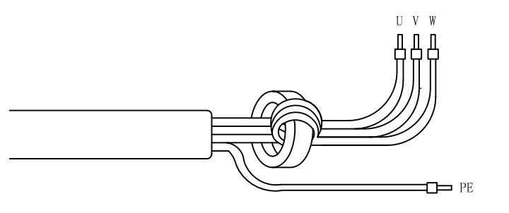
Ferrite magnetic ring, also referred to as the magnetic ring, can effectively absorb the radiation interference of the wire beam. The magnetic ring has different impedance characteristics at different frequencies. Generally, the impedance is very small at low frequencies. When the signal frequency increases, the impedance of the magnetic ring increases sharply, making it easy for normal and useful signals to pass through, and can effectively suppress high frequencies. The path of interference signals solves the problem of high-frequency interference suppression of power lines, signal lines and connectors. When the magnetic ring suppresses common mode interference, the eddy current loss of the magnetic ring to the high-frequency signal converts the high-frequency component into heat loss, so that a low-pass filter can be formed, so that the high-frequency noise can be greatly attenuated, and the impedance of useful signals at low frequencies can be ignored and does not affect the normal operation of the circuit.
The wire passing through the magnetic ring can be repeatedly wound on the magnetic ring to increase the inductance, thereby enhancing the use effect of the magnetic ring. But too many turns will make the loss too large and the temperature of the magnetic ring will rise too high. The recommended winding method and number of turns are as follows:
• Digital signal Cables Wrap the signal wire around the magnetic ring 2-3 times.
• Motor Power Cables Wind the U/V/W phase of the motor 2-3 times around the magnetic ring.
• The ground wire and the shielding net cannot be wound into the magnetic ring.
• Encoder Cables Wrap the encoder wire around the magnetic ring 2-3 times.