
How to Control 100 Servo Axes with EtherCAT at 100 Mbps?
In industrial automation, particularly in high-precision motion control applications such as industrial robots, CNC machine tools, and semiconductor equipment, EtherCAT (Ethernet Control Automation Technology) has been widely adopted. A common question is: how can EtherCAT support stable control of dozens or even hundreds of servo axes while achieving microsecond-level synchronization accuracy with a physical layer rate of just 100 Mbps? To understand this, it is necessary to examine EtherCAT communication mechanisms and system architecture. This capability is not determined by bandwidth alone, but is also closely related to its data processing approach, frame handling mechanism, and clock synchronization method.
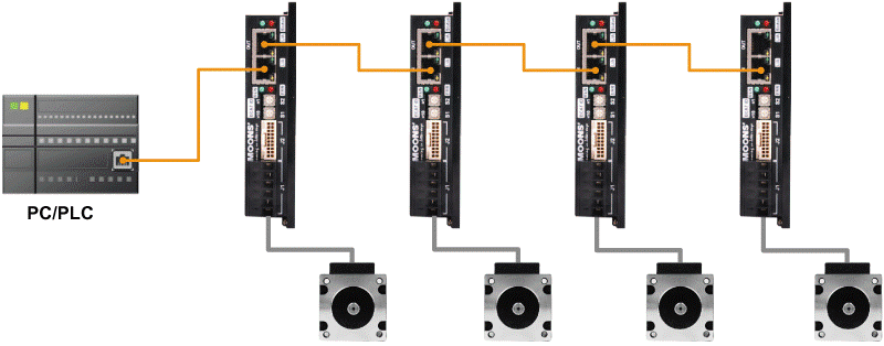
I. Efficiency Bottlenecks of Traditional Industrial Ethernet
To understand the advantages of EtherCAT, it is first necessary to examine the limitations of traditional industrial Ethernet. Protocols such as PROFINET and EtherNet/IP typically employ a store-and-forward mechanism, where the master communicates with each slave in a point-to-point manner. Each node must receive the entire data frame, process it via its CPU, and then forward it, resulting in cumulative processing latency. In addition, data encapsulation based on the TCP/IP protocol stack introduces extra overhead (approximately 40 bytes for the IP and TCP headers).
Consider an 8-axis servo system as an example. If each axis requires 100 bytes of data, the master must transmit and receive 8 frames, resulting in a total data volume of approximately 1600 bytes. As the number of axes increases, the number of communication frames grows linearly, leading to rapidly increasing bandwidth utilization. In addition, with a per-node processing delay of approximately 5–50 μs, overall synchronization accuracy is significantly impacted.
II. EtherCAT Core Mechanism: On-the-Fly Processing
EtherCAT fundamentally differs from traditional approaches by replacing the store-and-forward model with on-the-fly processing.
2.1 Working Principles: On-the-Fly Processing
Instead of using a store-and-forward approach, EtherCAT processes data in real time as the frame propagates through the network. The master sends a single Ethernet frame in which the process data of all slave devices are arranged sequentially by offset. As the frame passes through each slave, the EtherCAT Slave Controller (ESC) performs read and write operations directly on the data stream: it extracts control data addressed to the node and inserts feedback data into predefined locations. The frame then continues through the network and ultimately returns to the master. This entire process is executed in hardware without CPU involvement, resulting in a per-node processing latency typically in the range of 100–500 ns.
2.2 Frame Structure: High Payload Efficiency
EtherCAT improves payload efficiency by minimizing protocol overhead. A standard frame consists of an Ethernet header (14 bytes), an EtherCAT header (2 bytes), a process data field (up to approximately 1486 bytes), and a CRC (4 bytes). The process data field can map multiple slave devices contiguously. For a typical servo axis, the control word, target position, status word, and actual position require approximately 12–20 bytes per axis. Therefore, a 32-axis system requires roughly 384 bytes of data, which can be exchanged within a single 1500-byte Ethernet frame. In theory, this enables support for systems with hundreds of axes.
III. Distributed Clocks: Nanosecond-Level Synchronization
For multi-axis coordinated motion control, time synchronization accuracy is often more critical than data transmission rate. EtherCAT establishes a unified time base across the network through its Distributed Clocks (DC) mechanism.
3.1 Synchronization Principles: Unified Time Base
At system startup, a DC-capable slave device is automatically selected as the reference clock. The master measures the propagation delay of each node using a round-trip delay measurement mechanism and establishes a topology-dependent time offset model. During operation, the system periodically performs clock synchronization, dynamically compensating the local clocks of each slave device to suppress drift and maintain synchronization accuracy.
3.2 Performance Metrics: Synchronization Accuracy and Jitter
Under typical conditions, EtherCAT systems achieve synchronization accuracy within 1 μs, and under optimized conditions, accuracy can reach the 100 ns range. Synchronization jitter is typically controlled within 100 ns, while optimized systems can achieve ±35 ns. The system uses a 64-bit nanosecond-resolution time base (starting from January 1, 2000), meeting the time consistency requirements of high-precision motion control. In multi-axis systems, slave devices can trigger actions based on the unified time base, enabling deterministic synchronous control.
IV. Bandwidth Utilization: Improved Payload Efficiency
EtherCAT efficiency lies not only in its processing mechanism, but also in its efficient use of bandwidth. By reducing protocol overhead and increasing the data capacity of a single frame, it achieves a higher effective data ratio.
4.1 Protocol Stack Optimization
EtherCAT employs a lightweight protocol structure to minimize the overhead associated with traditional TCP/IP encapsulation. By carrying data from multiple slave devices within a single frame, it reduces the number of transmitted frames and improves bandwidth utilization.
| Features | EtherCAT | Traditional Industrial Ethernet |
| Protocol Overhead | MAC Layer + Physical Layer Only | Full TCP/IP Protocol Stack |
| Agreement overhead | < 10% | > 50% |
| Acknowledgment Mechanism | None | Required ACK/NACK |
| Retransmission Mechanism | None (handled in next cycle) | Yes (impacts real-time performance) |
4.2 Bandwidth Estimation
Taking a 1 ms control cycle as an example, at a physical layer rate of 100 Mbps, the theoretical data throughput is approximately 12.5 KB/ms. For a 100-axis system with 32 bytes per axis, the total data volume is about 3.2 KB, corresponding to roughly 25% bandwidth utilization. Even after accounting for protocol overhead and inter-frame gaps, sufficient bandwidth margin remains to support system expansion and stable operation. This indicates that EtherCAT retains significant bandwidth headroom even when controlling 100 servo axes.
V. Engineering Practice: Capacity Estimation and Design Boundaries
5.Typical Design Considerations
In system design, factors such as control cycle, per-axis data volume, network topology, and master performance must be considered to evaluate system capacity.
| Control Cycle | Recommended Axis Range | Synchronization Accuracy |
| 1ms | 100-200 axis | < 1μs |
| 500μs | 50-100 axis | < 500ns |
| 250μs | 20-50 axis | < 200ns |
5.2 Capacity Estimation Methods
Engineers can estimate system capacity using the following formula: Maximum axis count ≈ (cycle time × bandwidth) / data volume per axis. For example, with a 1 ms cycle time, 12.5 MB/s bandwidth, and 32 bytes per axis, the theoretical capacity is approximately 390 axes. In practice, considering protocol overhead, network topology, and real-time constraints, the system is typically limited to 200–300 axes.
VI. Comprehensive Characteristics of EtherCAT
6.1 Differences from Traditional Industrial Ethernet
Compared with traditional industrial Ethernet protocols that use a store-and-forward mechanism, EtherCAT differs significantly in data exchange methods, synchronization mechanisms, and system determinism.
| Feature | EtherCAT | PROFINET IRT | EtherNet/IP |
| Real-Time Mechanism | On-the-Fly Processing | TSN + Hardware Scheduling | CIP-based Software Protocol |
| Typical cycle | 100μs | 250μs-1ms | 1-10ms |
| Synchronization Accuracy | < 1μs | ~ 1μs | ~ 100μs |
| Topology | Line / Tree / Star | Dedicated Switch Required | Standard Switch Required |
| Bandwidth Utilization | > 90% | 60-70% | 30-50% |
6.2 Summary of Key Features
• Low latency: Hardware-based on-the-fly processing with node latency on the order of nanoseconds.
• High synchronization: Distributed Clocks enable sub-microsecond synchronization accuracy.
• High efficiency: Multi-node data exchange within a single frame reduces communication overhead.
• Flexible topology: Supports line, tree, and other network structures.
• Cost efficiency: Based on standard Ethernet physical layer, no dedicated switching hardware is required.
VII. Development Trends and Applications of EtherCAT
As industrial automation systems become increasingly complex, higher demands are placed on communication systems, including improved synchronization accuracy, larger-scale control capability, and stronger real-time performance.
EtherCAT continues to evolve through several extension technologies, including: EtherCAT G: Extends bandwidth to gigabit speeds to support larger-scale systems; EtherCAT P: Integrates power supply into the communication cable, simplifying wiring; Integration with TSN: Enhances time synchronization across heterogeneous networks.
EtherCAT demonstrates that efficiency optimization and architectural design are critical to system performance in industrial communication systems. Through on-the-fly processing, Distributed Clocks, and a lightweight protocol structure, it enables large-scale, high-precision synchronized motion control even with a 100 Mbps bandwidth. This design approach provides an efficient and scalable solution for complex automation systems.